Here are some scope shots. ADDEDPlease note that the test below is to determined how much this mostly magnet motor is affected by the Generator effect. I am not trying to make a Generator out of it. The first shot is with the motor working on a 1.3vdc input through a 1 Ohm shunt Resistor in series with probe 1 connected across it and probe 2 is across the coil. Both probe grounds are on the same side of the Resistor (standard current and voltage phase setup). Math function is on probe 1 x probe 2 The next shot is to test the motor as Generator, so now the mostly magnet motor coil is connected to a 10 Ohm load with probe 1 connected across the 1 Ohm series shunt and probe 2 is the voltage across the coil (same as above). I'm using the 12vdc motor (attached to flywheel) as primed mover. The input to the 12vdc motor is 380ma @ 12.63vdc = 4.8 Watts to turn it at the speed of the 2nd scope shot below. It looks to me that at that RPM (which is faster then the previous test) the Generator coil is outputting around 0.070 Watts To me it looks like the mostly magnet motor is not a good Generator considering the amount of input energy needed to the prime mover. However, we need to keep in mind that the 12vdc motor is operating at a much lower RPM then it was designed for, so it could get better. However there seems to be quite a difference. ADDEDDetails on the Coil: The mostly magnet motor coil has 4 Ohms DC resistance, made of about 0.8mm to 0.9mm magnet wire, wound bifilar connected in series. It has 19 milli Henry when at each ends of the core and 22.5 milli Henry when at center of core. The actual coil size (not including bobbin) opening is 14mm x 20mm and is 17mm wide Comments please Luc  Mostly Permanent Magnet Motor with minimal Input Power 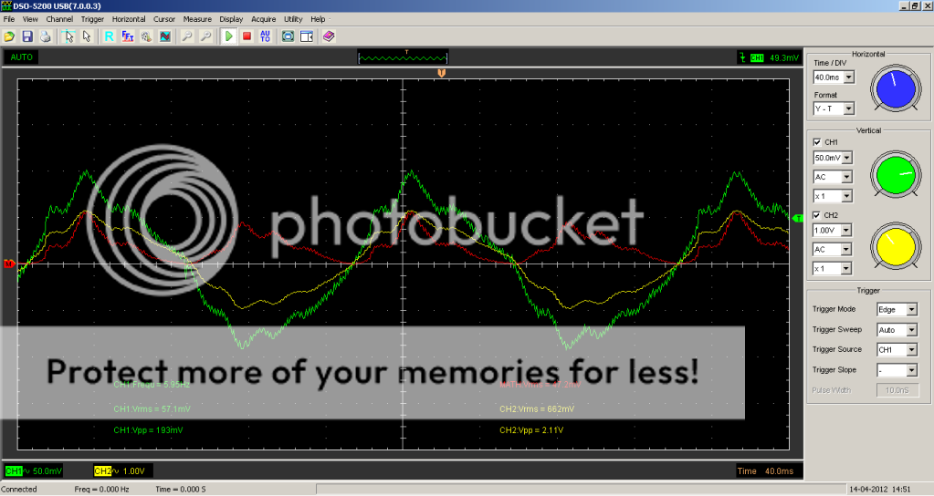 Mostly Permanent Magnet Motor with minimal Input Power
« Last Edit: 2012-04-14, 16:35:30 by gotoluc »
|
 Author
Topic: Mostly Permanent Magnet Motor with minimal Input Power (Read 17365 times)
Author
Topic: Mostly Permanent Magnet Motor with minimal Input Power (Read 17365 times)
