PopularFX
Home Help Search Login Register
Welcome,Guest. Please login or register.
2024-05-05, 14:37:20
News: If you have a suggestion or need for a new board title, please PM the Admins.
Please remember to keep topics and posts of the FE or casual nature. :)

Pages: 1 2 3 [4] 5 6 7
Author Topic: Comments on the McFreey paper  (Read 112850 times)

Group: Moderator
Hero Member
*****

Posts: 3366
Here the progress, both La and Lb are done, working on the copper ring (6mm od tube):
Hollow tube :(
   
Group: Guest
Itsu,

These are very nice coils.
For experimentation, it is always a good idea to have a ferrite core handy. The core should fit snugly into the opening of the coil. What kind of ferrite cores do you have?
As for the spiral, or even ring, I would not recommend tubing material. Bulk wire might be a better choice. I simply have no experience with tubing wires.
More than one turn is acceptable for systems similar to the one in Fig.6. For the system in Fig.7 a single turn (a ring) and a ferrite core in the coils is better, in my humble opinion.
Then, there is the choice of the material for the ring. Copper is only one possibility and it may not always work. The other choices are brass, zinc, aluminium and even alloys of iron. Remember, Leedskalnin apparently made a lot more electricity from iron than from copper.
The frequency of the magnetization field is also an important parameter. The precession once induced does not last forever. The T1 parameter, the spin-lattice relaxation time, is important and for copper it is very short. A quarter of the period of magnetization current has to be less than T1.

Isotope    Spin    T1 (s)      Abundance (%)
Cu65       3/2,    0.0004      70
Cu63       3/2,    0.0004      30
Zn67       5/2,    0.015        4
Fe57       1/2,    3               2
Ni61        3/2     0.05          1
Al27        5/2     0.03          100
   

Group: Elite Experimentalist
Hero Member
*****

Posts: 4102

Quote
Hollow tube :(


Quote
As for the spiral, or even ring, I would not recommend tubing material.

Now you tell me   :(

Ok,  hunting for a solid copper/brass ring

I have some 65x40x9 mm ferrite rings on order from Russia, those should fit snugly into the 68mm id of the coils.

Thanks for the info's

Regards itsu
   

Group: Moderator
Hero Member
*****

Posts: 3366
I have some 65x40x9 mm ferrite rings on order from Russia, those should fit snugly into the 68mm id of the coils.
Soft ferrite or hard ferrite (permanent magnet material) ?
   

Group: Elite Experimentalist
Hero Member
*****

Posts: 4102
Soft ferrite or hard ferrite (permanent magnet material) ?

I don't know, it did not say, only: permeability 2000.
When i got them i can compare the material with a similar sized ceramic ring magnet (loudspeaker) which would be hard ferrite i guess.
What do i need in my case (hard or soft)?

Regards Itsu


Group: Moderator
Hero Member
*****

Posts: 3366
I don't know, it did not say, only: permeability 2000.
Relative permeability of 2000 is associated with low coercivity (a.k.a. "soft").
Permanent magnets (e.g. hard ferrites, NdFeB, SmCo)) have high coercivity (10000s of Oersteds) and low relative permeability (around 1 like air)

What do i need in my case (hard or soft)?
Mostly soft, but for optional magnetic "DC biasing" you might need some ring/puck ceramic magnets (made out of hard ferrite) having the same diameter.

P.S.
Ceramic hard ferrite magnets are weaker but they have an advantage, in that they do not conduct electric current like e.g. NdFeB.  ...thus - no eddy currents, either.
   

Group: Elite Experimentalist
Hero Member
*****

Posts: 4102
Relative permeability of 2000 is associated with low coercivity (a.k.a. "soft").
Permanent magnets (e.g. hard ferrites, NdFeB, SmCo)) have high coercivity (10000s of Oersteds) and low relative permeability (around 1 like air)
Mostly soft, but for optional magnetic "DC biasing" you might need some ring/puck ceramic magnets (made out of hard ferrite) having the same diameter.

P.S.
Ceramic hard ferrite magnets are weaker but they have an advantage, in that they do not conduct electric current like e.g. NdFeB.  ...thus - no eddy currents, either.

So my Russian ferrite rings should be usefull for this device.

While waiting for them, and for a suitable brass/copper ring (they are hard to find), i continue working on my copper tube inner ring.
I made 2 and soldered them to a piece of double sided PCB making a solid ring again.

Finding the mechanicall resonance using a piezo microphone now worked much better.
It turns out to mechanical resonate at 3.071KHz (EM resonance at 63MHz).

Video here: http://www.youtube.com/watch?v=TVMuVZFdAi4&feature=youtu.be

Next i will fire up the La/Lb coil using the variac controlled welding transformer with this copper tube ring inside and make some measurements.

Thanks for the info/comments,  regards Itsu


Group: Moderator
Hero Member
*****

Posts: 3366
Very elegant setup Itsu.
Making the LaLb coils as two separate halves will allow you to easily turn one of them around, in order to experiment with the aiding and opposing flux modes in the core or ring placed between the two halves (see here).

I am surprised that you cannot find a large brass ring easily.
In my neighborhood there are a lot of hardware plumbing stores, that have large brass pipes, valves, tees, elbows, etc...  just waiting to be sliced up into nice rings with a hack-saw, etc...
   

Group: Moderator
Hero Member
*****

Posts: 3366
turns:              300 (9 layers of 34 turns)
You should always strive to wind an even number of "back and forth" layers, in order to nullify the longitudinal current and longitudinal magnetic field in toroidal and solenoidal coils. (see here)
   

Group: Tinkerer
Hero Member
*****

Posts: 3947
tExB=qr
That patent applies to inductors without ferromagnetic cores.
   

Group: Moderator
Hero Member
*****

Posts: 3366
The patent only illustrates nullification of longitudinal currents and resulting magnetic fields in toroidal coils. However, this concept is applicable to cored coils and solenoidal coils, too.
Even number of back-and forth layers nullifies these currents and fields better than odd number of layers and that is my main point.
   

Group: Elite Experimentalist
Hero Member
*****

Posts: 4102

Here some first test while waiting on the ferrite cores and a proper brass/copper ring.
(i did visit my local DIY shop, but could not find the proper sized ring i need, they all (plumbing stuff) are to small in diameter).

So i used my copper tube ring for now.

At 12V RMS across the 12V/21W load bulb and the La/Lb coil, i have 2.6A RMS running through the coil (0.1 CSR).
Total input is 83W divided over:

variac 4W
welding TR 18W
12/21 BULP 21W
rest (La/Lb coil / choke) 40W

No accurate voltage across the single turn was being induced, a noisy signal of about 10mV RMS was seen.

When cranking up the variac/welding tr. to its max., (using a 220V/60W bulb as load), i noted the following
values:

total input 470W
voltage across the bulb/coil 38V AC
current through the coil 8A RMS
induced voltage in the single turn coil 25mV RMS

Video here: http://www.youtube.com/watch?v=lfMc4mQu5qg&feature=youtu.be

Question: how to put in enough power into the single turn coil (like a short)?

 
Regards Itsu
   

Group: Tinkerer
Hero Member
*****

Posts: 3947
tExB=qr
Why not?  A loose / buzzing transformer and there you go.
Also, who's is to say that somebody more educated did not show him the principle.

Have you?
   

Group: Tinkerer
Hero Member
*****

Posts: 3947
tExB=qr
Please rephrase that.
There is no such thing as motion/translation of forces.   Forces cause motion, they are not in motion.

Move the point where the force is applied.
   

Group: Moderator
Hero Member
*****

Posts: 3366
Question: how to put in enough power into the single turn coil (like a short)?
Match the impedance of the secondary to the impedance of the the single turn coil (because of this principle).

In practice that means winding a 1-3 turn secondary winding with a very thick wire/strap (or several wires in parallel for the ease of wire bending and avoiding the skin-effect at HF).  
Take a look and study the construction of the secondary winding inside the type of a soldering iron that is illustrated below (the heating element in this type of soldering iron is like the low-impedance single turn coil)... and duplicate the same construction of the secondary winding around the ferrite core of a transformer used to power the single turn coil/ring.
« Last Edit: 2013-08-05, 12:54:29 by verpies »
   

Group: Moderator
Hero Member
*****

Posts: 3366
Have you?
No, I don't even speak Kapanadze's language.  I cannot communicate with him.
   

Group: Moderator
Hero Member
*****

Posts: 3366
Itsu,

Of course you should not drive the primary winding of the Impedance Matching Transformer (IMT), that powers the low-impedance single-turn coil/ring  (mentioned in my previous message), with your signal generator directly.

You can use this method to drive the primary winding of this IMT.
...but instead of using the TL494, you can use the your signal generator complementarly connected to two UCC27511 chips, driving two 600V Power Nch-MOSFETs.

The gapped TV yoke ferrite core might not be the most efficient core for the IMT (ferrite cores can handle high frequencies better than steel cores, though).

NOTE:  Two UCC27511 chips driving two 600V Power Nch-MOSFETs constitute a digital amplifier, used to boost the power of your signal generator (and to protect it as well).  
In this application, an analog amplifier would be more ideal, because it would be capable of applying an analog sine wave (a single frequency) to the primary of the IMT and eventually to the single-turn ring,  but such an analog amplifier would be much more difficult to construct (and much more expensive).  
Let's hope that the odd harmonics of the rectangular wave introduced by a digital amplifier, will not throw a monkey wrench in the whole scheme.
« Last Edit: 2013-08-05, 15:13:43 by verpies »
   

Group: Tinkerer
Hero Member
*****

Posts: 3947
tExB=qr
No, I don't even speak Kapanadze's language.  I cannot communicate with him.

You stated:

"Why not?  A loose / buzzing transformer and there you go."

If it is so easy, where is your version?
   

Group: Moderator
Hero Member
*****

Posts: 3366
In my drawer.  I've decided to go with two pairs of 300x12mm brass and steel disks for the electromechanical spool motor.
I wrote that this acoustic principle is easy to stumble upon by an uneducated person, not that it's easy to build purposely.
« Last Edit: 2013-08-05, 15:14:47 by verpies »
   

Group: Elite Experimentalist
Hero Member
*****

Posts: 4102

You can use this method to drive the primary winding of this IMT.

Nice, where have i seen that thing before  :)

I did by the way improve on it like you mentioned then, and now it has more symmetrical primary windings, each primary covering the whole circumference forth and back of the yoke.

I will give it a try.

Regards Itsu  
« Last Edit: 2013-08-05, 18:08:22 by Itsu »
   
Group: Guest
"Why not?  A loose / buzzing transformer and there you go."

You are absolutely right, Grumpy.
This is suggested in Fig. 4.
   
Group: Guest
...  
In this application, an analog amplifier would be more ideal, because it would be capable of applying an analog sine wave (a single frequency) to the primary of the IMT and eventually to the single-turn ring,  but such an analog amplifier would be much more difficult to construct (and much more expensive).  
Let's hope that the odd harmonics of the rectangular wave introduced by a digital amplifier, will not throw a monkey wrench in the whole scheme.

This is an important remark.
   

Group: Moderator
Hero Member
*****

Posts: 3366
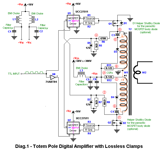
In order not to dissipate the energy of these drain spikes as heat in voltage clamps (a.k.a. snubbers) you can use lossless clamps instead.  
These clamps recycle the drain spikes' energy back into the power supply, instead of wasting it in RC or Zener or Transorb "heaters".


DESCRIPTION:
1) Primary windings of T2 are wound bifilarly (e.g. with double-wire speaker cable or two parallel Litz wires - better).
2) Q1 and Q2 are N-ch power MOSFETs rated for blocking voltages of at least 2*V2A.
3) Two fast rectifier diodes (e.g. Shottky) are needed for an effective operation of lossless clamps. These diodes (D3 and D4) must be capable of handling the pulsed currents occurring in the primaries (T2,W1AB) and must be rated for at least 2*V2A.
4) Two capacitors (C3 & C4) in the μF range (the more μF the better) are used as a floating DC sources (=V2A) for the lossless clamps. They can be ceramic or electrolytic capacitors (or both types connected in parallel), but must have low-ESR and be rated for at least V2A.
5) Pins #6 of the UCC27511 drivers (U1 and U2) are used to ensure that two power MOSFETs (Q1 and Q2) are not conducting both at the same time. The voltage on pin #6 must be above 2.4V in order for the driver to be enabled (this happens only when the opposite MOSFET stops conducting. This is sensed by R6 and R8).
6) R11 and R12 are optional Current Sensing Resistors (CSRs) used for troubleshooting (they must be of non-wirewound type and non-inductive!).  The waveform across these resistors should have a sawtooth shape. If this waveform is rectangular, then it is an indication of insufficient number of turns in primary windings (too low inductance of T2,W1ABCD) or an input frequency that is too low.  These resistors can also serve as current limiters/fuses that protect Q1 and Q2 from excessive current damage.
7) If the U0 Hex Inverter is used, then all of its unused inputs (pins #3,5,7,9,11,13) must be grounded and its power supply pin #14 must be connected to +5V DC and bypassed with a suitable capacitor to pin #7 (this is not shown on the schematic!).  If the U0 inverter is unavailable, instead of it, it might be possible to use an improvised inverter composed of a small BJT (or MOSFET) and additional resistors.
8) Diodes D6 and D9 are used with a low-power isolation transformer (T1) in order to protect the inputs of U1 and U2 from negative voltages (they can tolerate only -0.3V).  These diodes can be low current/power but they must have a reverse recovery time (trr) that is sufficiently fast to support the maximum input frequency applied to T1.
9) An absence of a varying input signal during the presence of V1A and W2A supply voltages will result in damage to T2,W1AB windings or Q1,Q2 transistors because T2 is incapable of handling DC applied to its primaries.
10) The rules of connections layout for U1 and U2, described in the UCC27511 Datasheet in section "PCB Layout" on page 22, should be followed strictly.

P.S.
To maximize the efficiency of lossless clamps, the T2 primary winding W1A should have the same length, turns and placement as the winding W1C and should be interleaved with it. By the same token, the winding W1B should have the same length, turns and placement as the winding W1D and should be interleaved with it (all of this is automatically ensured when those windings are wound bifilarly with e.g. a speaker cable consisting of two parallel wires).  The only permitted difference between the windings is the wire thickness - because windings W1C and W1D conduct less average current than W1A and W1B, they can be wound with a thinner wire.

Of course, for best results the windings of all toroidal transformers should be wound in 2 layers (or a higher even number) where each layer uniformly covers one full outer circumference of the the core (see this diagram for what happens if it does not).
Each layer should be advanced in the opposite direction to the next layer (also along the full outer circumference of the core), while keeping the turn direction constant (e.g. CCW) for all layers.
If more layers are needed then use an even number of layers (e.g. 2, 4, 6, 8, etc...) alternating the direction of winding advancement along the circumference of the core, for each successive layer.  

On schematics below, the beginning of each wire in the 2-wire bifilar cable, that constitutes the primary windings, is marked with a full dot of a different color.
« Last Edit: 2014-05-01, 16:09:37 by verpies »
   
Group: Elite
Hero Member
******

Posts: 3537
It's turtles all the way down
Verpies

Nice job on the schematics and text presented. Looks like you are an experienced switchmode designer. Good to have you here. I appreciate your careful work.


---------------------------
"Secrecy, secret societies and secret groups have always been repugnant to a free and open society"......John F Kennedy
   

Group: Elite Experimentalist
Hero Member
*****

Posts: 4102

I used my old "Dally replication" transformer driver (yoke transformer driven by a TL494) equiped with an extra heavy gauge 2 turn wire to drive my single turn (made of solid copper wire now) coil.

This single turn coil gets lukewarm when operating.

Frequency range of the TL494 is from 1.5KHz to 94KHz.

The used yoke is a solid ring, so no gaps, and the both primaries are speaker wire wound forth and back (so 2 layers each) covering the whole circumference of the yoke.

Video here: http://www.youtube.com/watch?v=cvDu83s-JzU&feature=youtu.be

I will try various single turn coils / tubes to see if any abnormalities can be observed while sweeping through the TL494 frequency range.

Regards Itsu
   
Pages: 1 2 3 [4] 5 6 7
« previous next »


Home Help Search Login Register
Theme © PopularFX | Based on PFX Ideas! | Scripts from iScript4u 2024-05-05, 14:37:20