PopularFX
Home Help Search Login Register
Welcome,Guest. Please login or register.
2026-08-21, 23:00:03
News: Forum TIP:
The SHOUT BOX deletes messages after 3 hours. It is NOT meant to have lengthy conversations in. Use the Chat feature instead.

Pages: [1]
Author Topic: Discussion about acquiring high permeability ferrites for plasma experiments  (Read 551 times)
Group: Ambassador
Hero Member
*****

Posts: 4753
Here some suggestions for sourcing such materials .
**Topic under construction while information is added on some suggested vendors.••
   

Group: Administrator
Hero Member
*****

Posts: 4698


Buy me some coffee
Ok passing a message on from Mark via Chet

You can see model FN200 has a permeability of 2000 and its spells out the other characteristics see attached image.

this is a webpage you can use to send enquiries to over 300 manufacturers and the drawing you sent would be good to show them
https://www.made-in-china.com/quality-china-product/productSearch?word=ferrite+rod+u2000&bv_id=1jvkn8ouba5e&pbv_id=
They all speak great english
My people in China do not specialize in Magnetic materials but are willing to help one to identify the supplier that meets your needs
There are thousands of suppliers not just 300
« Last Edit: 2026-08-16, 00:13:53 by Chet K »
   
Group: Ambassador
Hero Member
*****

Posts: 4753
Peter
thanks for posting that information from Mark Dansie ,
Below is screenshot of the spec sheet/information (CMD5005) from one vendor I contacted at Verpies suggestion in US

So CMD5005 are the specs we are aiming for as we find sources in Marks links !
Here the complete spec sheet on one alternative ferrite .

Page 04 has the overview of their ferrites

Page 15 has the specifics on this FN200 ferrite ( mentioned in previous post.)

https://ferrite.ru/upload/iblock/056/zeeewjiglt6szh3gb20r2tw16tje8a16/New%20Catalog%20of%20Careful.pdf

Respectfully
Chet K
PS
these materials are for the spider core experiments which Itsu has started to build and we need some high permeability ferrite components to complete .
A dedicated thread for this will be hosted in itsu’s bench.


Group: Administrator
Hero Member
*****

Posts: 4866
...and we need some high permeability ferrite components to complete .
High permeability is desirable but so is the lack of degradation of this permeability at higher frequencies.
Also, in order to carve out a monolithic spider shape without air-gaps requires a huge chunk of ferrite.  The maximum manufactured chunk size (before they cut it up) is an information that only the OEMs know and it is very hard to come by.
   
Group: Ambassador
Hero Member
*****

Posts: 4753
Also, in order to carve out a monolithic spider shape without air-gaps requires a huge chunk of ferrite.  The maximum manufactured chunk size (before they cut it up) is an information that only the OEMs know and it is very hard to come by.
Verpies,
Hopefully this coming week will show a path towards these OEM’s…so as to get some quotes on a monolithic chunk appropriate to the task .
Mark D gives the impression there are many more than the link he forwarded !

What would be a good size for the spider core blank ?
And should we consider submitting a spider core rendering … for a quote on finished monolithic core ?

At the moment this center core piece is on the list .
And toroid size for arms ( prior to machining)

To note above is for possibility of building on a budget ( as Itsu has started) , and also there was mention of soft iron .03 mm(?) Enameled wire,
Bundled to the required spider core shape ?( for cost savings and getting more access to experimenters.


Group: Administrator
Hero Member
*****

Posts: 4866
What would be a good size for the spider core blank ?
A 6" cube.

And should we consider submitting a spider core rendering … for a quote on finished monolithic core ?
We could but it would raise some eyebrows.

At the moment this center core piece is on the list .
And toroid size for arms ( prior to machining)
Yes because it is easier to obtain.

To note above is for possibility of building on a budget ( as Itsu has started) , and also there was mention of soft iron .03 mm(?) Enameled wire,
Bundled to the required spider core shape ?( for cost savings and getting more access to experimenters.
Yes, a bundled enameled fine iron wire would be the poor man's substitute for a ferrite.
   

Group: Mad Scientist
Hero Member
*****

Posts: 1246
   

Group: Mad Scientist
Hero Member
*****

Posts: 1246
metglass makes a tape or say bendable strips. make a plan and form a spider core with it. 

mags
   

Group: Mad Scientist
Hero Member
*****

Posts: 1246
https://metglas.com/magnetic-materials/

the cost of having to make such a core via machining and cost of materials, this plus time to cut and configure i would say it could be a great core.

mags
   
Group: Ambassador
Hero Member
*****

Posts: 4753
https://metglas.com/magnetic-materials/

the cost of having to make such a core via machining and cost of materials, this plus time to cut and configure i would say it could be a great core.

mags

I remember this being discussed earlier ( somewhere)
The characteristics of laminations were not lining up with Device requirements for the best possible results, and I remember being perplexed as to the recommendation of an inexpensive.03mm soft enameled iron wire “was” acceptable…. Apparently soft iron (.03 mm ( bundled)) has properties which are quite interesting and appropriate for this Spider core.. and other (Hubbard ,Mag-vid and (a few others I can’t recall ATM))
Chet
   

Group: Administrator
Hero Member
*****

Posts: 4866
metglass makes a tape or say bendable strips. make a plan and form a spider core with it. 
A tape will not mesh in the center post without air gaps.  The center post cannot be composed of parallel planar layers.
Metglass tape is very brittle.  It's name does not contain the word "glass" for nothing.
   

Group: Mad Scientist
Hero Member
*****

Posts: 1246
A tape will not mesh in the center post without air gaps.  The center post cannot be composed of parallel planar layers.
Metglass tape is very brittle.  It's name does not contain the word "glass" for nothing.

well if 'glass' is non magnetic, what is the material mixed with it that is?


mags
   

Group: Renaissance Man
Hero Member
*****

Posts: 3123


Buy me a cigar
Could a 3Dprinted hollow form be produced and filled with a suitable mixture of materials to suit the experiment? Happy to print off some forms if required.
Cheers G.


---------------------------
Nanny state ? Left at the gate !! :)
   

Group: Administrator
Hero Member
*****

Posts: 4866
well if 'glass' is non magnetic, what is the material mixed with it that is?
It is not mixed with anything non-metallic.  It is a pure ferrous alloy that has been chilled so quickly that it did not have the time to crystallize.  The resulting structure is amorphous - like glass.

The way this is usually done is by pouring a thin stream of molten metal on the outside of a rapidly rotating silver drum chilled with liquid nitrogen (or LH) from inside and thus forming a thin flat strip of Metglass with irregular edges that are trimmed later..  Silver's excellent thermal conductivity absorbs the heat out of the molten metal so quickly that it does not have the time to crystallize.  The best results occur in vacuum because the chilled silver surface of the drum accumulates frost from the air, otherwise.  When the molten metal hits it, frost flashes to steam and ruptures the forming strip and inhibits fast heat absorption by the chilled silver surface.
   

Group: Administrator
Hero Member
*****

Posts: 4866
Could a 3Dprinted hollow form be produced and filled with a suitable mixture of materials to suit the experiment? Happy to print off some forms if required.
You could cast that shape without a problem. 
You could even use the same ferrous alloys that Metglass uses (e.g.: Fe₈₀B₂₀, Fe₇₈Si₉B₁₃, Fe₆₇Co₁₈B₁₄Si₁, Fe₆₆Co₁₈B₁₄Si₂, Co₆₆Fe₄Mo₂Si₁₆B₁₂, Fe₄₀Ni₄₀Mo₄B₁₈, etc...) but the excellent magnetic properties of these alloys are not manifested without the rapid freezing.

Even if you could somehow rapid-freeze the melt, it would not work at higher frequencies because of eddy currents developing in it due to the bulk conductivity of these alloys.
That is why non-conductive ferrites or fine enameled iron wire bundles are required to eliminate the undesirable eddy currents.  Enameled Metglass wire bundles would be the best but such things are not manufactured anywhere.
   
Group: Ambassador
Hero Member
*****

Posts: 4753
Verpies,
Going to start soliciting from Dansie’s vendor list,

https://ferrite.ru/upload/iblock/056/zeeewjiglt6szh3gb20r2tw16tje8a16/New%20Catalog%20of%20Careful.pdf

Below is the data sheet for ferrite spec submittal .
Also the attached file for the actual dimensions of center core and toroids .

Is this all relevant information for submittal ?
For clarity only the specs will be submitted not the mentioned vendor or part numbers .
   
Group: Professor
Hero Member
*****

Posts: 2519
The measurements presented in the datasheet that Chet shows—aside from the complex permeability curve—are taken at 10 kHz, even though the datasheet is titled “High-frequency Ni-Zn ferrite.” At Metglass, we sometimes see “1 kHz” cited as the starting point for their “high frequencies”. It’s very interesting to get a sense of the orders of magnitude of the parameters of commercially available materials, but when it comes to practical applications, the issue of frequency is just as critical as permeability, and that’s what will determine the choice, based on the desired loss criteria.


---------------------------
"Open your mind, but not like a trash bin"
   

Group: Administrator
Hero Member
*****

Posts: 4866
Is this all relevant information for submittal ?
For clarity only the specs will be submitted not the mentioned vendor or part numbers .
Yes, although the loss of CMD5005 ferrite increases an order of magnitude between 10kHz and 1MHz it is good enough.
If a comparable ferrite material comes up that has the same (or greater) initial permeability with lower decrease / losses at higher frequencies then it will be an added bonus.
   

Group: Administrator
Hero Member
*****

Posts: 4866

For clarity only the specs will be submitted not the mentioned vendor or part numbers .
At low frequency, a ferrite's permeability is a simple real number - that's the "initial permeability" (µᵢ) quoted as a single spec (2100 for CMD5005). But as frequency rises, the domain-wall motion and spin-precession mechanisms that produce that permeability can't keep up instantaneously with the applied AC field. The material's response develops a phase lag behind the drive field, so permeability has to be treated as a complex quantity:
µ = µ' − jµ"

  • µ' (the real part) describes the in-phase component — the part that stores magnetic energy and gives you inductance. At low frequency µ' is essentially flat and equal to the DC/low-frequency initial permeability.  On this plot the curve is labeled µᵢ instead of the cutomary µ' (it is µᵢ, extended out over frequency).
  • µ" (the imaginary part) describes the out-of-phase, lossy component - energy dissipated as heat (hysteresis, eddy current, and resonance losses) rather than stored. At low frequency µ" is small; it rises and typically peaks as µ' begins to roll off with increasing frequency.

The two curves together tell you the useful frequency range of the ferrite:

Below the "knee" (where µ' is still flat [500kHz] and µ" is low), the ferrite behaves as a good, low-loss inductive/transformer core - this is the region where CMD5005 is recommended for broadband transformers.
As frequency increases toward and past where µ' starts dropping, µ" rises and eventually exceeds µ' - the material is now dissipative rather than inductive. This is the regime where the same ferrite becomes useful as an EMI suppression bead/absorber instead of as an inductor core.
   
Group: Ambassador
Hero Member
*****

Posts: 4753
Yes, although the loss of CMD5005 ferrite increases an order of magnitude between 10kHz and 1MHz it is good enough.
If a comparable ferrite material comes up that has the same (or greater) initial permeability with lower decrease / losses at higher frequencies then it will be an added bonus.

Verpies
Thanks for reply.. and further explanation.
  It is my understanding (regarding these experiments) that this spider core
Topology is really not a common or well understood realm of experimentation…

I did attach a few comments earlier with possibly similar configurations ( Stephens' MAGVID, Alfred Hubbard's, André Coutier's and Paul Brown's devices have been mentioned over the last year, ( I also understand no such claims are being made…

The big attraction with almost all the members who followed the Spider core experiments, was the opportunity to experiment in a configuration which brought several unusual ( to most members) elements together. Magnetism, low-pressure plasma (a not so aggressive vacuum… and the plausibility of creating an electron trap ..? To change the environment into ???

One key point being all manner of elements and experiments ( from atmosphere to ….Materials that Deliver small charges or emissions In our environment .

This IMO is an enormous learning tool for the FE community…
And most (all) I have spoken with completely agree .

Verpies
Have I properly explained the Experiment parameters and plausible expectations?

Respectfully submitted
Chet
   

Group: Administrator
Hero Member
*****

Posts: 4866
It is my understanding (regarding these experiments) that this spider core
Topology is really not a common or well understood realm of experimentation…
I think it is well understood since it relies on the good ol' Lorentz force, but indeed this field configuration does not occur very often in experimentation because it is conflated with a bipolar rotating magnetic field of a polyphase AC induction motor, which has been beaten to death already (experimentally) ...especially at low frequencies.

I did attach a few comments earlier with possibly similar configurations ( Stephens' MAGVID, Alfred Hubbard's, André Coutier's and Paul Brown's devices have been mentioned over the last year,...
Yes, there are similarities to these devices because they all create a unipolar rotating magnetic field with a central pole.
Their fields have the same effect on free electric charges as the blades of two counter-rotating fans have on air molecules:
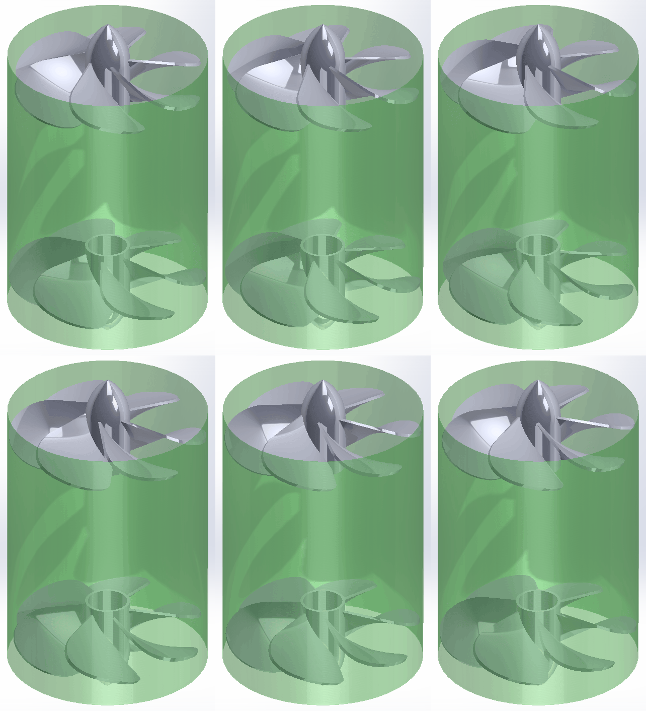

The spider core is a simplification of that principle as it creates an effect of only one "fan".
Simpler things are usually easier to experiment with.


The big attraction with almost all the members who followed the Spider core experiments, was the opportunity to experiment in a configuration which brought several unusual ( to most members) elements together. Magnetism, low-pressure plasma (a not so aggressive vacuum...
Low pressure plasma is a picturesque source of free charge carriers (gas ions) that can depict the charge acceleration in real time.
But plasma in a fishbowl is not the only way to see what is happening inside.  Charged dust or Lycopodium spores can be used for visualization, too.

One key point being all manner of elements and experiments ( from atmosphere to ….Materials that Deliver small charges or emissions In our environment .
These materials are convenient sources of free charged particles that do not require high voltages.
All freely moving charged particles are similarly affected by the Lorentz "fans".  There are differences, though, depending on their mass to charge ratios and signs.

… and the plausibility of creating an electron trap ..? To change the environment into ???
Trapping these accelerated charge carriers in orbits by a static magnetic field is an additional (and optional) mechanism that is explicitly stipulated only by the MAGVID.
When the charges are not allowed to loop and return, theoretically this can lead to permanent charge depletion and hyperionized state of matter.
The consequences of that state is another can of worms.  I would rather discuss it after we get there.

Have I properly explained the Experiment parameters and plausible expectations?
Moreless.  I still have this impression that many people conflate the unipolar rotating magnetic field with the bipolar one and this creates disinterest because bipolar rotating magnetic fields are so ubiquitous in polyphase AC induction motors.

   Bipolar rotating magnetic field.
   
Pages: [1]
« previous next »


Home Help Search Login Register
Theme © PopularFX | Based on PFX Ideas! | Scripts from iScript4u 2026-08-21, 23:00:03
