PopularFX
Home Help Search Login Register
Welcome,Guest. Please login or register.
2024-05-17, 12:36:54
News: A feature is available which provides a place all members can chat, either publicly or privately.
There is also a "Shout" feature on each page. Only available to members.

Pages: [1] 2 3 4
Author Topic: Fighters "Romanian ZPM (Zero Point Module) replication.  (Read 7717 times)

Group: Moderator
Hero Member
*****

Posts: 4102


I am playing around with the "Romanian ZPM (Zero Point Module)" circuit from member "fighter" (from BeyondUnity.org forum) see his thread (still on AboveUnity.com) here: https://www.aboveunity.com/thread/romanian-zpm-zero-point-module/

See his diagram here:


My both coils are (also) on an AMCC-200 core (Metglas) but are 100 and 200 turns of 0.8 mm magnet wire with a DC resistance of resp. 0.9 and 1.5 Ohm.
Measuring the both coils separately for inductance (when both are on the core) using my Agilent U1733C LCR meter, shows at 10kHz an inductance of about 280mH (200 turns) and 90mH (100 turns), see pictures:


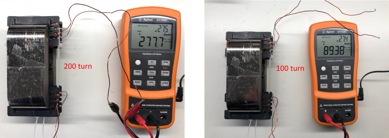
But when measuring at 100kHz, on the 200 turns coil, the meter switches over to capacitance (like 41pF) or when fixing the meter to inductance i get negative inductance values (like -53mH) on that meter.
Similar when measuring the 100 turns coil.

So i used my nanoVNA to plot the inductance of the 200 turn coil and got the following plots (for inductance versus frequency, see upper graph):


At 10kHz (see marker 1) it corresponds with the value measured by my LCR meter (280mH), but then it fluctuates rather strongly and ends up negative to 500kHz as shown.
I was wondering why and found a convincing answer i think here:  https://www.eevblog.com/forum/beginners/explain-inductance-vs-freq/msg1586398/#msg1586398
where it says:

In ideal inductor, the L is constant.
If you make an air core inductor this will hold true.
If you put a magnetic material in the mix, things get complicated.
Now your core material will dominate the inductance.
Depending on its properties, you will see different L at different frequencies.
To complicate things even more, the total impedance of your inductor is modified by ESR of the wire, losses in the magnetic material and capacitances of the coil.


When adding a series capacitance plot to the measurement (see lower graph for capacitance versus frequency in the above plots) we see a flip from negative capacitance to positive capacitance around 40kHz, meaning we flip from how the coil behaves itself from inductance to capacitance.
With other words, the coil start acting like a capacitor.


I will further build up the circuit and try to make some measurements........

Regards Itsu

   
Group: Experimentalist
Hero Member
*****

Posts: 1987
Hi Itsu

I think a negative inductance is a positive capacitance when viewed as an inductor. I don't think you can measure an inductance with a VNA nor with an inductance meter when the circuit is a mixture of inductances and capacitors (those related to inter-coil capacitances).

It is the impedance of the whole that must be measured, Z = R+jX. If the imaginary part X is positive, it is an inductance, otherwise it is a capacitance. The complex impedance is obtained from the measurement of the parameter S21, but in this type of measurement I don't have much practice with my nanoVNA to tell you more now.

On the other hand, can you specify the ground connection on your diagram?


---------------------------
"Open your mind, but not like a trash bin"
   

Hero Member
*****

Posts: 545
Itsu, could you take a few marker measurements of both inductance and capacitance at various frequencies?
200kc, 300kc, 400kc, and especially that odd negative region 340-360kc.

If both inductance and capacitance are reading negative, then the coil might actually be acting as a left-handed / negative-index meta-material in that frequency band. O0


---------------------------
"An overly-skeptical scientist might hastily conclude by scooping and analyzing a thousand buckets of ocean water that the ocean has no fish in it."
   
Group: Experimentalist
Hero Member
*****

Posts: 1688
Itsu,

That is a large capacitance value of nearly 2nfd at ~335kHz for 200 turns of 20ga wire in that coil configuration!  Have you measured the self resonant frequency of the 200T coil?

Also, with the running configuration of the circuit involving the bucking of the 2 coils located on the ends of the core, there will be a relatively large so-called leakage inductance.  This makes the analysis of the overall circuit very complex especially with the parameters you measured with the VNA.

Interesting!

Regards,
Pm


Group: Moderator
Hero Member
*****

Posts: 4102
Hi Itsu

I think a negative inductance is a positive capacitance when viewed as an inductor. I don't think you can measure an inductance with a VNA nor with an inductance meter when the circuit is a mixture of inductances and capacitors (those related to inter-coil capacitances).

It is the impedance of the whole that must be measured, Z = R+jX. If the imaginary part X is positive, it is an inductance, otherwise it is a capacitance. The complex impedance is obtained from the measurement of the parameter S21, but in this type of measurement I don't have much practice with my nanoVNA to tell you more now.

On the other hand, can you specify the ground connection on your diagram?


Hi F6,

Quote
I think a negative inductance is a positive capacitance when viewed as an inductor.
I don't think you can measure an inductance with a VNA nor with an inductance meter when the circuit is a mixture of inductances and capacitors (those related to inter-coil capacitances).

As a coil consists of both inductance and capacitance, you basically say that we cannot measure a coil with a VNA.

I know that a VNA uses some basic signals it captures (amplitude and phase of a high-frequency signal) and that the built-in computer in the VNA calculates key parameters such as return loss and insertion loss of the network under test.
It is also capable of visualizing the results in different formats—for example, real/imaginary, magnitude/phase, Smith chart, etc.
From:  https://www.sciencedirect.com/topics/computer-science/vector-network-analyzer


Concerning the ground connection, it's not my diagram, it's from member Fighter, but when reading that thread i linked, one can read that there seems to be some problems with the ground as the scope probes / FG used probably are the only grounding points which can lead to ground loops and wrong measurements.

Suggestions as using an isolated scope/FG and/or using differential probing were given in that thread to mitigate the problems encountered (like powering up full a 12V/5W bulb while the PS used shows 25V @ 0mA
at a frequency of 604kHz, see this post video around the 4 min mark:  https://www.aboveunity.com/thread/romanian-zpm-zero-point-module/?order=all#comment-4b4524d9-81b1-4605-b930-aa71010a436b

Itsu
   

Group: Moderator
Hero Member
*****

Posts: 4102
Itsu, could you take a few marker measurements of both inductance and capacitance at various frequencies?
200kc, 300kc, 400kc, and especially that odd negative region 340-360kc.

If both inductance and capacitance are reading negative, then the coil might actually be acting as a left-handed / negative-index meta-material in that frequency band. O0


Hakasays,

see below graph with some extra markers. Not sure which marker data (right side) you want, so i toke marker 7 which has a negative capacitance but obviously a (small) positive inductance.

Indeed, that negative region 340-360kc is odd, as one (i) would expect to see similar fluctuations on the inductance as on the capacitance.

But it seems that never i have an "inductance and capacitance are reading negative" situation as far as i can see.


Here a zoomed in (325kHz to 370kHz) with more data points (1601 instead of 101)  picture:
(not sure how accurate this nanoVNA is in this situation).


Itsu
   

Group: Moderator
Hero Member
*****

Posts: 4102
Itsu,

That is a large capacitance value of nearly 2nfd at ~335kHz for 200 turns of 20ga wire in that coil configuration!  Have you measured the self resonant frequency of the 200T coil?

Also, with the running configuration of the circuit involving the bucking of the 2 coils located on the ends of the core, there will be a relatively large so-called leakage inductance.  This makes the analysis of the overall circuit very complex especially with the parameters you measured with the VNA.

Interesting!

Regards,
Pm


Hi PM,

no, i did not yet measure the self resonances of the coils, but will do that later today / this week.

I will also see if i can measure the leakage inductance and the coupling coefficient.

Member Fighter did report some strange behavior with this circuit, so it probably comes from this complex combination of metglas core and series connected opposing coils on the end of the core together with the grounding problems.

I will see if i also get these problems.

Itsu

   
Group: Experimentalist
Hero Member
*****

Posts: 1987

Hi F6,

As a coil consists of both inductance and capacitance, you basically say that we cannot measure a coil with a VNA.

Of course not. What I mean is that you can't measure inductance when the parasitic capacitances are not negligible, i.e. represent a non-negligible impedance at the observed frequency, which is certainly the case of the large coils seen on the picture at frequencies of several tens to hundreds of KHz, in addition with conductive cores adding more capacitances.  At hundreds KHz the capacitances are surely the preferred path followed by the signal.

Otherwise of course you can measure a pure capacitance or a pure inductance with a VNA, but the bigger the parasitic capacitances are, the bigger the measurement error will be, until nothing correct is indicated anymore. How else do you explain your negative inductance?

Quote
Concerning the ground connection, it's not my diagram, it's from member Fighter

The question was about your setup. What point do you use for the ground? Is it at the source of Q1?

Quote
but when reading that thread i linked, one can read that there seems to be some problems with the ground as the scope probes / FG used probably are the only grounding points which can lead to ground loops and wrong measurements.

Suggestions as using an isolated scope/FG and/or using differential probing were given in that thread to mitigate the problems encountered (like powering up full a 12V/5W bulb while the PS used shows 25V @ 0mA
at a frequency of 604kHz, see this post video around the 4 min mark:  https://www.aboveunity.com/thread/romanian-zpm-zero-point-module/?order=all#comment-4b4524d9-81b1-4605-b930-aa71010a436b

Itsu

I think this is a good suggestion, grounds are indeed a real problem, all the time (I had one recently).  What JohnStone says in his post of 23 June 2019 sounds interesting too.
I think the 25 V DC source should be decoupled with a RF capacitor (0.1 to 1 µF), as we have no idea what impedance it is at high frequencies.


---------------------------
"Open your mind, but not like a trash bin"
   

Group: Moderator
Hero Member
*****

Posts: 4102

Quote
Of course not. What I mean is that you can't measure inductance when the parasitic capacitances are not negligible, i.e. represent a non-negligible impedance at the observed frequency, which is certainly the case of the large coils seen on the picture at frequencies of several tens to hundreds of KHz, in addition with conductive cores adding more capacitances.  At hundreds KHz the capacitances are surely the preferred path followed by the signal.

Otherwise of course you can measure a pure capacitance or a pure inductance with a VNA, but the bigger the parasitic capacitances are, the bigger the measurement error will be, until nothing correct is indicated anymore. How else do you explain your negative inductance?

Ok, i see what you mean, that is the same as the answer i found in the linked comment in my 1st post from eevblog:

I was wondering why and found a convincing answer i think here:  https://www.eevblog.com/forum/beginners/explain-inductance-vs-freq/msg1586398/#msg1586398
where it says:

In ideal inductor, the L is constant.
If you make an air core inductor this will hold true.
If you put a magnetic material in the mix, things get complicated.
Now your core material will dominate the inductance.
Depending on its properties, you will see different L at different frequencies.
To complicate things even more, the total impedance of your inductor is modified by ESR of the wire, losses in the magnetic material and capacitances of the coil.


Quote
The question was about your setup. What point do you use for the ground? Is it at the source of Q1?

well, i have not build up the circuit yet, i only have the 2 coils on the metglas core which i now measure for inductance, resistance, resonance etc.
So no ground problem here yet.


Itsu
   

Group: Moderator
Hero Member
*****

Posts: 4102
Measuring the inductance of the coils while shorting to other coil shows the leakage inductance and then calculate the coupling coefficient (CC) using:
https://www.e-magnetica.pl/calculator/magnetic_coupling_coefficient


100 turn coil   86mH @ 10kHz gives 6.6mH when shorting the 200 turn coil:   CC = 0.96
200 turn coil 270mH @ 10kHz gives  20mH when shorting the 100 turn coil:   CC = 0.96

Self resonance 100 turn coil = 40.7kHz
Self resonance 200 turn coil = 37.7kHz

Putting the both coils in series aiding and opposing gives the following inductances:

Series aiding:     655mH  @ 10kHz
Series opposing:  63mH  @ 10kHz

This last configuration (series opposing) is the one which is being used in the circuit.

Self resonance of this series opposing configuration gives a 1st peak at 37.7kHz (2nd at 350kHz) which 1st peak is the same as the self resonance of the single 200 turn coil!


Itsu
« Last Edit: 2022-10-26, 20:44:54 by Itsu »
   

Group: Moderator
Hero Member
*****

Posts: 4102
Using the nanoVNA to plot some graphs of this series opposing configuration:

# inductance    showing the 10kHz start inductance at 63mH
# capacitance
# impedance     showing the impedance peaks (parallel resonance) at 44.3kHz and 323kHz.


itsu
   
Group: Experimentalist
Hero Member
*****

Posts: 1987
@Itsu

Z = R + jX. The impedance consists of a real and an imaginary part, the resistive part and the reactive part, and you have only one curve. What do you really show?  Its modulus, √(R²+X²)?


---------------------------
"Open your mind, but not like a trash bin"
   

Group: Moderator
Hero Member
*****

Posts: 4102
The R of the both coils are resp. 0.9 and 1.5 Ohm as mentioned above and measured with my DMM, so R of this series opposing configuration will be 2.4 Ohm or so.

I can put up as 3rd graph "Freq R Jx S11" which both shows the R and the Jx graph, but i put up the "Freq impedance S11" graph just to indicate where the resonance peaks are.
I have no idea how this nanoVNA app calculates this impedance Z S11.

I measured the present graphs in the "series measurement" setup which is not for a low impedance environment, so i have to remeasure (recalibrate etc.) the setup to be in "shunt measurement".
https://www.mwrf.com/technologies/test-measurement/article/21849791/copper-mountain-technologies-make-accurate-impedance-measurements-using-a-vna
 

I am more worried about the position of Q1 (MOSFET) in the in the first post shown diagram.    I think it should be reversed (drain - source).


Itsu   
   
Group: Experimentalist
Hero Member
*****

Posts: 1688
@Itsu

Z = R + jX. The impedance consists of a real and an imaginary part, the resistive part and the reactive part, and you have only one curve. What do you really show?  Its modulus, √(R²+X²)?

This equation is for a simple ideal inductor with no internal capacitance.  The correct equation with internal capacitance is Z = R + j𝛚L/(1-𝛚^2LC) .

Pm
   
Group: Experimentalist
Hero Member
*****

Posts: 1688
The R of the both coils are resp. 0.9 and 1.5 Ohm as mentioned above and measured with my DMM, so R of this series opposing configuration will be 2.4 Ohm or so.

I can put up as 3rd graph "Freq R Jx S11" which both shows the R and the Jx graph, but i put up the "Freq impedance S11" graph just to indicate where the resonance peaks are.
I have no idea how this nanoVNA app calculates this impedance Z S11.

I measured the present graphs in the "series measurement" setup which is not for a low impedance environment, so i have to remeasure (recalibrate etc.) the setup to be in "shunt measurement".
https://www.mwrf.com/technologies/test-measurement/article/21849791/copper-mountain-technologies-make-accurate-impedance-measurements-using-a-vna
 

I am more worried about the position of Q1 (MOSFET) in the in the first post shown diagram.    I think it should be reversed (drain - source).


Itsu

Yes you are correct.  With the polarity shown, the conventional current would always flow thru the substrate diode.  IOW, the Q1 would always conduct with or without gate drive.

Edit: Perhaps they actually used a P-channel mosfet which would work properly in this configuration but incorrectly show an N-channel.

Pm
   

Group: Moderator
Hero Member
*****

Posts: 4102
PM,  thanks,

yes, this intrinsic Body Diode would act as if the MOSFET is always active this way.
But even without such a diode, the gate signal would have to be 4 or 5V higher than the source voltage (25V here) to be able to activate the MOSFET which would mean 30V or so.
But then when switching on the MOSFET would put the source to ground level and thus the gate - source voltage to be 30V which might blow the MOSFET (typical 20V).


Anyway, i found out which MOSFET he uses (IRF3205ZPBF so N-channel) and how it really is connected (so wrong as shown on the diagram above) here:
https://www.aboveunity.com/thread/romanian-zpm-zero-point-module/?order=all#comment-a34ffa77-6081-4aee-a5a0-aa7500ba4ee1


Itsu
   
Group: Experimentalist
Hero Member
*****

Posts: 1987
This equation is for a simple ideal inductor with no internal capacitance.  The correct equation with internal capacitance is Z = R + j𝛚L/(1-𝛚^2LC) .

Pm

This is wrong, my equation is for the general case. I have not given the impedance of an inductor or a capacitor. Z = R+jX is the impedance in the general case.
Besides you should understand this from your own equation, that here X = 𝛚L/(1-𝛚^2LC). Your equation does not contradict mine, it is only a special case.

And as already said, if the imaginary part X is positive, it is an inductance, otherwise it is a capacitance. You have to realise what this means. It doesn't mean that there is only a pure inductance or a pure capacitance in the circuit, it means that at the two input terminals of your circuit, you will only see an inductance OR a capacitance, never both at the same time at a given frequency. The measured value, equivalent to only one inductance or one capacitance, will depend on the values of the real inductances and capacitors used in the circuit.

A black box with two terminals is a dipole, and its impedance at a given frequency is R+jX whatever the real passive elements inside, which R and X will depend on.


---------------------------
"Open your mind, but not like a trash bin"
   

Group: Moderator
Hero Member
*****

Posts: 4102
I put together the below shown circuit.

The first diagram is the basic circuit as i understand Fighter was using.
I am using a 12V battery at first (without any filtering) as the circuit produces many spikes and peaks which did affect my PS (i believe that was also the problem (OU) Fighter had).
My PS was already damaged earlier by such a circuit, so no risk taken for now.

With the battery, i can make some scope shots of this spiky signal to show the problem.
Later on, i can add some filtering and use my PS instead.

Second picture is the real circuit i am using right now


Group: Moderator
Hero Member
*****

Posts: 4102

I made a first run with this present circuit, monitoring the input voltage, current and power while sweeping the frequency from 1kHz to 1MHz.

Input from a 12V, 7AH battery without any filtering on the input.

Voltage and current monitored via 2 DMM's as well via the scope with yellow probe across the battery input and the blue probe across the 1 Ohm CSR in the return line to the battery.

The screenshot shows the Blue input current, the yellow input voltage and the red power via the math function.

The 3x 5W bulbs (15W) pull around 9W initially at low frequency and decrease with up going frequency, but no special effects like sudden decrease in input voltage, current or power are noticed.


Video here:   https://youtu.be/955-n_SasF8


I will now measure the signals across the bulbs to see how they compare to Fighter's signals.

Itsu
   
Group: Tech Wizard
Hero Member
*****

Posts: 1124
Hi Itsu,

The voltage back spikes that your scope shows appearing across the 12 V battery (with their both positive and negative 20 - 25 V peak amplitudes) may indeed fool even a laboratory power supply if it is not designed for pulsed operation, feeding such switched resistor + inductive loads. 
It is interesting what Fighter wrote on his forum here with respect to his ZPE circuit:
https://www.beyondunity.org/thread/public-answer-to-chris/?p=4&order=all#comment-9bd08b3c-e71a-471a-828b-af360090bfea  I quote:

"From my experience a diode placed on the input could not stop ZPM to send power back to the DC source.
ZPM "see" the DC source as a load and is sending power back to it.
The diode (even a very fast one) get very hot and is burned. I don't know why.
"

So he inserted a diode in series with the input supply rail and it got burnt. One possible explanation for this is that during the negative back spikes the high peak currents they caused via the diode exceeded the specs of the diode.  The built-in current meter of the PS showed only some tens of mA (30-50 mA) current in the 300 - 400 kHz switching frequency range he used for the circuit because the spikes may have influenced the internal circuit for the meter . The series diode in the supply rail may have conducted indeed in the reverse direction driven by the negative back spikes if Fighter's circuit also produced those your scopeshot above clearly shows.

He also used 3 pieces of 9V alkaline batteries in series to replace his entire PS and he wrote the batteries got warm and their voltage dropped down fast and the battery tests remained inconclusive.   

These are the pieces of information from which I suspect the internal current meter got fooled and showed only less than 50 mA output current taken by his ZPE circuit. 

Your measurements seem correct and I think they show reality. Thanks for showing your efforts.

Gyula 

Edited for more clarity.
« Last Edit: 2022-10-30, 22:57:21 by gyula »
   

Group: Moderator
Hero Member
*****

Posts: 4102
Hi Gyula,

thanks for your insights, yes there are some spikes on the (unfiltered) input, see here a better screenshot of the 12V input signal.


My PS also did show some strange behaviour and noises so i went for using a battery at first.

I will try to insert a series diode to see what it does, but i think Fighter mentioned more heating problems in other components as well.

I am slowly reading forward in his thread to see how things developed there, but up till now my setup is behaving rather normally, even the DMM's (voltage / current) i put in the input circuit.

Itsu
   
Group: Experimentalist
Hero Member
*****

Posts: 1688
Itsu,

Since the bucking coils have different individual inductances, you might try reversing the leads to the coil assembly to see if the current pulse to the power supply changes polarity at the mosfet turn off.

Regards,
Pm
   

Group: Moderator
Hero Member
*****

Posts: 4102
PM, thanks for the suggestion, i will do so.

But i was measuring the different currents in the circuit and found something i did not expect.

The below picture shows the points where i measured the currents (blue, purple and green).

I expected to see that the total input current (blue) would be the sum of the both currents through resp. the lamps (purple) and the coils (green).

But it does not, so i wonder where i make a mistake, in either my mind or in my measurements.

Blue is voltage probe across the 1 Ohm csr,
purple is AC only current probe (current has no DC component),
green is AC / DC current probe.

Frequency was 330kHz.


Itsu
« Last Edit: 2022-10-31, 16:49:26 by Itsu »
   
Group: Experimentalist
Hero Member
*****

Posts: 1688
Itsu,

It would appear that the probe polarity for CH3(pur) measuring the lamp current is reversed from what it should be.  If so, then the sum of CH3 and CH2 would equal CH4.

Regards,
Pm
   

Group: Moderator
Hero Member
*****

Posts: 4102
PM,

i added the current probe direction on the above picture.

So what you are saying is that the lamps current flow from bottom to top?

Itsu
   
Pages: [1] 2 3 4
« previous next »


Home Help Search Login Register
Theme © PopularFX | Based on PFX Ideas! | Scripts from iScript4u 2024-05-17, 12:36:54