... ok ... first things first. This is an attempt at a replication, as I have stated on the build thread at mooker.com.
...and I want your build to succeed. I am contributing to this by pointing out rookie theoretical and engineering mistakes to you based on the
component phenomena that I am familiar with. I don't claim to know all of the phenomena that go on in this device, but I do know some of them.
Hubbard built this, not me, I'm copying what Hubbard did based on a very small amount of information that we were left.
Exactly, this device was built 106 years ago in times when clear photographs in newspapers were minor miracles.
These grainy photos show us only the outermost coil.
There is a professionally made sketch from these times that depicts 9 coils inside this device (in addition to the outer coil). The newspaper of the time named it the Hubbard coil (note the singular) because that is what was visible on the outside.

Since this is a sketch and not a photograph, its subject matter was first processed by a human brain.
Sketches can, by their very nature, depict simplifications and interpretations of their maker.
If the sketcher is not the inventor, the potential for misinterpretations is huge.
For example, the sketch depicts one central object surrounded by a circular pattern of 8 other cylindrical objects.
These objects are assumed to be "electro-magnets" or helical coils wound on some kind of cylindrical formers (or cores) on the basis of the following newspaper quote:
"In general, he says, it is made up of a group of eight electro-magnets,
each with primary and secondary windings of copper wire,
which are arranged around a large steel core.
The core likewise has a single winding.
About the entire group of cells is a secondary winding."Note, that the passage
"each with primary and secondary windings of copper wire" implies that these "electo-magnets" are in fact transformers and practical transformers don't work with DC so the current flowing through these windings must be PDC or AC.
Also, the phrase "electro-magnets" imply that there is some kind of magnetic field generated by these objects in response to the flow of electric current. This implies magnetic interaction. ...and because the windings are in such proximity - near-field magnetic interaction.
Because the sketch is so grainy, you assume that the coils' formers are steel tubes since the sketcher has drawn circles where their ends would be.
Since DC is practically excluded and PDC or AC is implied, the steel tubes/pipes seem to be only your misguided interpretation. I write 'misguided" because you are not "guiding" your interpretations with physical knowledge, i.e. you are not considering the physical effects of steel tubes inside of windings carrying PDC or AC, such as the eddy currents and hysteresis losses.
Furthermore, the higher the frequency of current flowing in these windings, the smaller the probability that these coils are wound on solid steel tubes because of these losses (these phenomena were all alive and well in 1919).
To mitigate the eddy currents, slots could be cut in the steel tubes but that does nothing to mitigate their hysteresis losses.
So what were the copper coils wound on ?
There are two groups of answers depending whether the inventor wanted to maximize or minimize the magnetic flux generated by these "electro-magnets"/transformers:
1) If he wanted the magnetic flux to be minimized while retaining low losses at high current frequencies, he would have made them air-core coils ...or coils wound on non-conductive paramagnetic or diamagnetic materials such as Bakelite or glass or even cardboard or dry wood.
2) If he wanted to make good transformers, he would aim to maximize the flux and flux amplitude by using highly permeable cores of low conductivity.
A boy in 1919 would have only three classes of materials at his disposition that meet the latter requirements: Steel/Iron laminations, wire or powder since contemporary ferrites have not yet been discovered in 1919.
Out of these 3 forms of steel/iron, enameled wires or laminations are the easiest to deal with. Binding and insulating from each other the individual grains of iron powder is a major hassle that is sometimes justified by the isotropicity of the resulting material. Otherwise iron powder yields cores of inferior permeability if high pressure sintering is not used without binders.
Since laminations are hard to form into cores of circular cross sections, this leaves enameled steel/iron wires as the prime candidate for fashioning highly permeable cylindrical cores which are anisotropically non-conductive.
If you look at this grainy sketch again you might be able to see the ends of a bundle of small wires protruding out of the coils ...or just a scanning noise.
Using iron wire bundles for fashioning cylindrical permeable cores does not preclude the existence of thin coil formers made out of non-conductive paramagnetic or diamagnetic materials such as plastic, ceramic or glass.
NOTE: If in your rebuttal of the analysis above you are intending to use the drawings or words from the 1983 replication of this device, don't even start because this replication was subject to the same misinterpretations of the source material.
If you believe I've made a furnace, then by extension Hubbard made a furnace...
Not at all because the key ingredients necessary to make an inductive furnace (i.e.: eddy currents and hysteresis losses) would only be created in a build based on your misguided interpretation of that sketch.
Secondly, the secret to OU is to understand that Howard Johnson was right.
How do you know ?
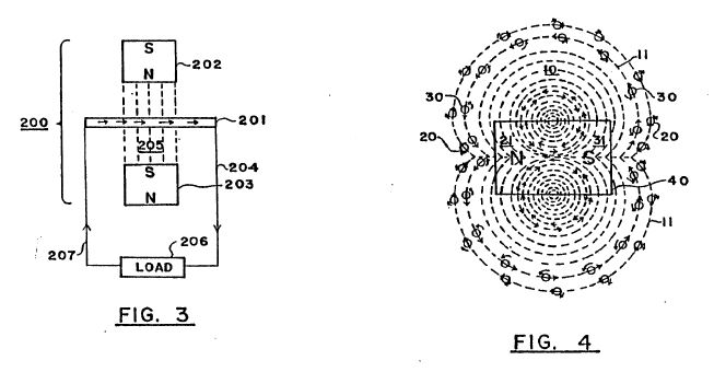
There is a second inverted magnetic field operating within a magnet, both inner and outer magnetic fields spin in opposite directions.
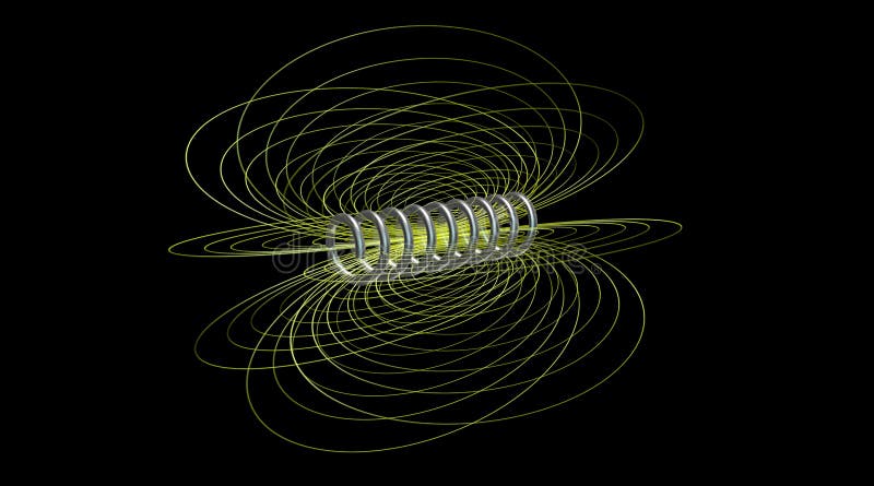
This is an ambiguous statement because it is not clear from it whether it is the entire magnetic field that spins, like this:

...or individual flux lines that spin (J.Newman style) like this:
Free energy is easy, ask an intelligent question...
Which one did you mean ?
Anyway, according to mainstream science, magnetic field does not spin by itself but it does influence the spin of material particles, e.g. electrons.
Get past the native outside N|S field and you get the underlying S|N field (with it's opposite spin) - this is where gravitic properties exist as well.
I don't know what you mean. I think it's time to make a drawing of the fields in your theory. e.g. like this:

I've been hearing for years now that a coil wound as follows has some gravitic properties ...but I have never seen it confirmed.

Counterwound coils are the chief differentiators, and feature in almost every design that reportedly yielded OU results... Robert Adams, Floyd Sweet, Don Smith, etc...
If you can get past the S|N barrier, the reward is zero point.
This makes no sense - flux lines form closed loops that do not intersect, not a barrier.
Free energy is easy, ask an intelligent question...
Anyway, when you write "counterwound", which of the following coils do you mean ?

How do these coil topologies make a difference ? It's time to stop speaking in generalities without explaining them !
Hubbard (I believe) was able to create a square wave by combining resonant wire lengths in the centre, middle and outer coils.
Wave of what ?
Wires of any length do not create any square waves by themselves, so how is any wave generated by this device ?
Wires of some lengths interact with some wavelengths of electric field like this:
Free energy is easy, ask an intelligent question...
This square wave effectively turns on and off a magnetic field in the middle coils over the output tube at a precise moment
First explain, what generates the magnetic field that is interrupted ?
So how does your interpretation of the Hubbard work?
You are not ready for it. First you have to muddle through what you came up with.
This time answer all of my questions directly. It is easy to identify them because they have question marks at their ends. Author
Topic: Free energy is easy, ask an intelligent question... (Read 16493 times)
Author
Topic: Free energy is easy, ask an intelligent question... (Read 16493 times)
