PopularFX
Home Help Search Login Register
Welcome,Guest. Please login or register.
2026-08-14, 21:52:04
News: A feature is available which provides a place all members can chat, either publicly or privately.
There is also a "Shout" feature on each page. Only available to members.

Pages: 1 2 3 4 [5] 6
Author Topic: Bucking Coils  (Read 2251 times)

Group: Elite Experimentalist
Hero Member
*****

Posts: 4848
Maybe phase is not the best way to get delay time in this instance, sorry about that.  Any chance of having a fast leading edge pulse and seeing the delay from that?

I appreciiate all you are doing on Q measurements and hope that work improves results from this bench.

Smudge

Smudge,

i tried it earlier with fast pulses, but there are no valid responses as far as I can see.

Here i use a fast leading edge pulse of about 600ps (does not registrate on my data for some reason) in yellow, which is put into the primary (no delay lines active) and in purple the response on the secondary:


So i do not see a valid secondary pulse on which i could measure the difference with.

Itsu
   

Group: Administrator
Hero Member
*****

Posts: 4856
Here i use a fast leading edge pulse of about 600ps (does not registrate on my data for some reason) in yellow, which is put into the primary (no delay lines active) and in purple the response on the secondary:
The purple trace seems to manifest a disturbance before the first rising edge of the yellow trace  ...as if the effect preceded the cause.
Is you probing deskewed ?
   

Group: Moderator
Hero Member
*****

Posts: 2434
The purple trace seems to manifest a disturbance before the first rising edge of the yellow trace  ...as if the effect preceded the cause.
Is you probing deskewed ?
I have seen this type of disturbance apparently occurring earlier than the instigating pulse on oscilloscopes in the past, and put it down to the length of the coax 'scope leads where you can get a travelling wave both inside the coax and one travelling along the outside of the coax.  The outside wave travels faster then the inner one, so if the outside wave can influence what the scope is seeing you get this apparent early effect.  I would be inclined to try a ferrite ring around the probe lead for the secondary and see if this eliminates the early effect.
   

Group: Elite Experimentalist
Hero Member
*****

Posts: 4848
The purple trace seems to manifest a disturbance before the first rising edge of the yellow trace  ...as if the effect preceded the cause.
Is you probing deskewed ?

It was not  O0  i normally have my differential probe at channel 3 (purple), but changed it to the normal voltage probe yesterday, but probably the skewing characteristics of the different probes are not reset when reattaching a probe, so i guess there was still an old skew factor active.

I have reset the skewing and now the screenshot looks better:


There still is some (premature?) pulsing visible which disturbs the scope time delay measurement function (it looks for the first rising pulse between the 2 signals), so i had to do it by cursors as best as i can, which seems to show a 560ps delay between the 2 traces.
Mind you this is WITHOUT delay lines active, so a base measurement.

There however are still the OPEN delay line coils around each half of the core, so perhaps they interfere with the measurement (causing these premature purple pulses).
I can remove those open delay line coils, but then its much harder to make further delay line active measurement.


Itsu
« Last Edit: 2026-05-03, 12:56:09 by Itsu »
   

Group: Elite Experimentalist
Hero Member
*****

Posts: 4848
Instead of the OPEN delay lines, i now reattached the (42) 100pF smd caps to the return line, so we now have a 100pF delay line active.

Doing the same measurement as above, we now see the time delay increase from 560ps to 620ps between the yellow peak and the purple peak:


Itsu
   

Group: Moderator
Hero Member
*****

Posts: 2434
Instead of the OPEN delay lines, i now reattached the (42) 100pF smd caps to the return line, so we now have a 100pF delay line active.

Doing the same measurement as above, we now see the time delay increase from 560ps to 620ps between the yellow peak and the purple peak:


Itsu
There is something I don't understand here.  The 560pS delay along the open core I can accept, but only a 60pS increase with the delay line active doesn't seem right.  You previously measured 52uH for a 6 turn coil so a single turn coil would be 1.444uH.  A delay line of 20 sections where each has L=1.44uH and C=100pF gives a time delay of 12nS per section (t=sqrt(L*C), a total time of 0.24uS for 20 sections.  Can you use a rectangular pulse with your fast rise time and look to see whether the output is then a sort of rectangular pulse but with that 0.24uS delay?  Perhaps use 1uS pulse width and say 1KHz prf.

Smudge
   

Group: Administrator
Hero Member
*****

Posts: 4856
Can you use a rectangular pulse with your fast rise time and look to see whether the output is then a sort of rectangular pulse but with that 0.24uS delay?  Perhaps use 1uS pulse width and say 1KHz prf.
Well, you asked for a fast rise time and he has delivered a pulse that rises in picoseconds.  I think this is as good as it gets.
Getting a rectangular pulse with such edge characteristics is unrealistic.
   

Group: Elite Experimentalist
Hero Member
*****

Posts: 4848
Smudge,

i used your suggestion and dialed 1us long 5V DC rectangular pulse with a PRF of 1kHz on on my FG.
This pulse is the best my FG can do, and its edge is way slower than the pico-pulse i used earlier which is not from a FG, but from a homemade gadget which only produces the shown yellow pulse in that earlier post. 

This is the result with NO coil attached, just the FG output on the scope:


This is the same pulse, but now connected to the primary:


We see some disturbance coming up.

Now see what happens when i add a 2nd probe to the secondary:


Where or what should i use for a starting point for measure the time delay between the yellow (primary) and blue (secondary) signals?
Remember, this is without any delay line active (coils are there, but open).

Itsu
« Last Edit: 2026-05-06, 09:24:18 by Itsu »
   

Group: Administrator
Hero Member
*****

Posts: 4856
Are these voltage waveforms ACROSS INDUCTOR ?
   

Group: Elite Experimentalist
Hero Member
*****

Posts: 4848

Screenshots 2 and 3, yes.

Screenshot 2 is yellow across the primary, screenshot 3 is yellow across primary, blue across the secondary.

Screenshot 1 is just yellow across the FG only.


Group: Moderator
Hero Member
*****

Posts: 2434
I can see something like 40+ nS delay which is far more than the 560 pS from your earlier measurement.  I take the time between halfway up the leading edge of the applied pulse (1V) and the 1V point of the leading edge of the output pulse.  I have access to earlier work conducted by Graham Gunderson while employed by Chava LLC where I find the measured delay was 34.8nS.  This earlier work was not looking at bucking coils, but had the secondary loaded with a capacitor where theory suggested the input at the primary might exhibit negative resistance.  My job was analysing all the results, so I have a wealth of information that could benefit these present explorations.  I will now publish this work in a separate thread, but here I put one of my papers that shows the similarity with Itsu's set up.  I also include a paper that shows a measurement I did on a smaller toroid.

Smudge
   

Group: Elite Experimentalist
Hero Member
*****

Posts: 4848
Smudge,


Quote
I can see something like 40+ nS delay which is far more than the 560 pS from your earlier measurement.  I take the time between halfway up the leading edge of the applied pulse (1V) and the 1V point of the leading edge of the output pulse.


I "zoomed in" on that specific area and this is the result (just the FG and yellow probe at the primary and the blue probe at the secondary):


So the time delay (without active delay line) is 43.5ns measured at that specific point.

Why the pico-pulser measured the 560ps i don't know, perhaps the ferrite is reacting different at faster pulses?

Itsu


Group: Elite Experimentalist
Hero Member
*****

Posts: 4848
When i use the same setup and scope settings, but instead of the FG driving the primary coil i use the pico-pulser, i get this result:


This clearly shows a different reaction to the pico pulse and the purple vertical cursors measure a difference at the same 1V points of 1ns, which probably by zooming in further decrease more to the earlier measured 560ps.

Itsu
« Last Edit: 2026-05-06, 14:08:39 by Itsu »
   

Group: Moderator
Hero Member
*****

Posts: 2434
It strikes me that your homemade gadget producing the picosecond pulse is sending something via a ground loop.  Can you tell us what this gadget is and how it is connected?  The signals from your FG are giving respectable results, and it will be interesting to see what happens when the delay line capacitors are connected.

Smudge
   

Group: Elite Experimentalist
Hero Member
*****

Posts: 4848

Quote
It strikes me that your homemade gadget producing the picosecond pulse is sending something via a ground loop

Perhaps the open delay line coils?

Quote
Can you tell us what this gadget is and how it is connected?

this pico pulser is build around the LT1073 and the specific circuit can be found on page 14 of this datasheet: https://www.rlocman.ru/i/File/2023/04/14/lt1073.pdf


Quote
The signals from your FG are giving respectable results, and it will be interesting to see what happens when the delay line capacitors are connected.


Ok, i will use the FG as source (1us pulse at 1kHz rpf) and put the 100pF smd capacitors delay line on.   
The "lumped constant delay.PDF" shows that the secondary was terminated with 47 Ohm load, is that needed or wanted?

Itsu
   

Group: Elite Experimentalist
Hero Member
*****

Posts: 4848
100pF delay line active, same setup and scope setting as in the last screenshot of my post #107 (1us pulse 1kHz PRF):


Again here the problem where to measure the delay.

Itsu
   

Group: Elite Experimentalist
Hero Member
*****

Posts: 4848
Here the difference between WITHOUT and WITH the 100pF delay line active, but now both with a 50 Ohm load at the secondary:


The difference at the 1V point is about 136ns (86ns WITHOUT D.L., 222ns WITH D.L.).


Itsu
   

Group: Moderator
Hero Member
*****

Posts: 2434
In that last measurement the mid point of the rising edge of the blue trace is some 200nS from the input yellow trace, and that is of the order that I calaculated in a previous post.  I am OK with that and would expect a sinusoidal input to show a phase delay commensurate with that order of time delay.

Having looked back I see that I started a topic about using magnetic delay on 6th March 2019 that didn't get anywhere.  I then started another topic on 23rd September 2019 where Itsu did much work similar to what he has done here.  There I posted much more information and I had forgotten about that.  That work ceased on 20th August 2023.  I would point out that the work does show that we can create magnetic delay, and it seems theoretically possible to obtain excess energy using that delay by various means of which the bucking coils is but one possibility.  (Incidentally bucking coils were looked at in that previous Itsu work, and I had forgotten that).  Regarding where the excess energy comes from I have long held the belief that the electron spins that create the magnetic fields in permeable material can be a source of energy if we could get somewhere in the system the Lenz H field or mmf from the load current in the secondary to NOT be 90 degree shifted from the B field or flux.  Electrical delay lines with appropriate terminations have the ability to create differing phase between voltage and current along the line, hence a magnetic one should also have this ability with respect to mmf and flux.

Smudge 
   

Group: Administrator
Hero Member
*****

Posts: 4856
@Smudge

Please guide Itsu how to integrate these waveforms so the input and output energy can be compared.
Me thinks, he will need current waveforms, too.
   

Group: Elite Experimentalist
Hero Member
*****

Posts: 4848
For what its worth, i switched to the TDS 3054B scope which has 2 P6302 current probes attached besides the 2 voltage probes.
It was powered on for some hours and a fresh calibration was done.

I still have the 100pF delay lines active.

I hooked up the yellow voltage probe and the green current probe to the primary.
I hooked up the blue voltage probe and the purple current probe to the secondary which has the 50 Ohm load resistor.

The FG was still set at 1us pulse with a 1kHz prf and 5V DC.

As this scope can make 1 math calculation at a time, i took 2 screenshots with the math function (red trace) set to first calculate input power yellow x green over 1 cycle (screen) followed by the math function (red trace) calculating the output power blue x purple also over 1 cycle (screen).

Results can be seen here:
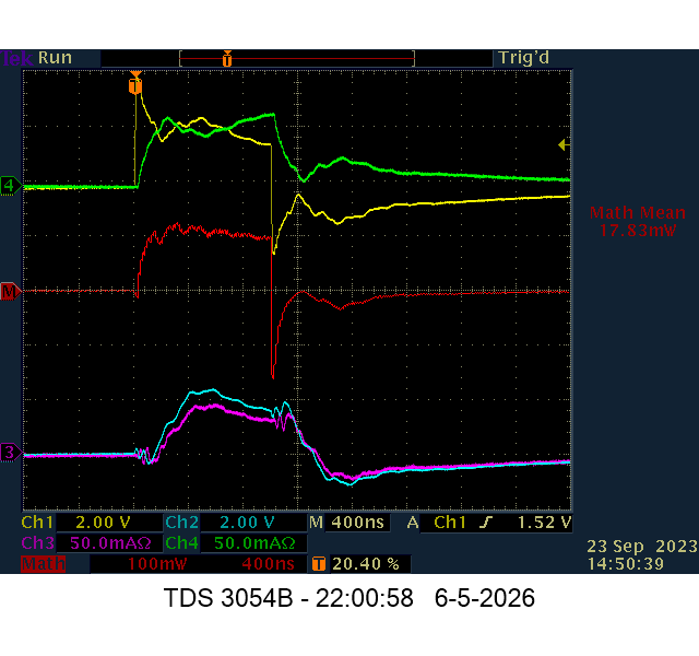

Input power 1 cycle
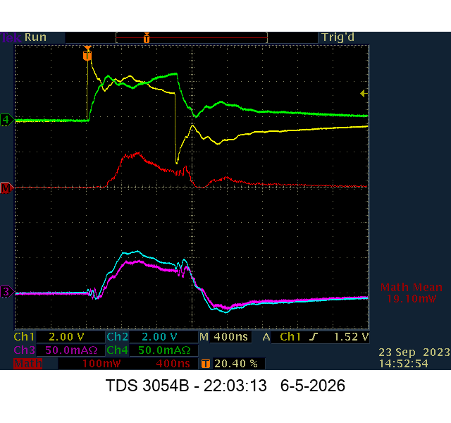


Output power 1 cycle


Then i increased the shown cycles and set the FG to prf 150kHz and toke the same measurements over multiple cycles:
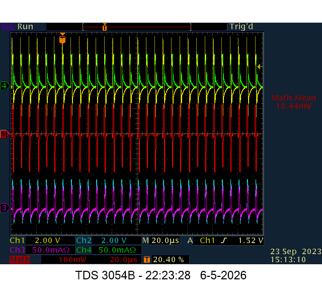

Input power multiple cycles
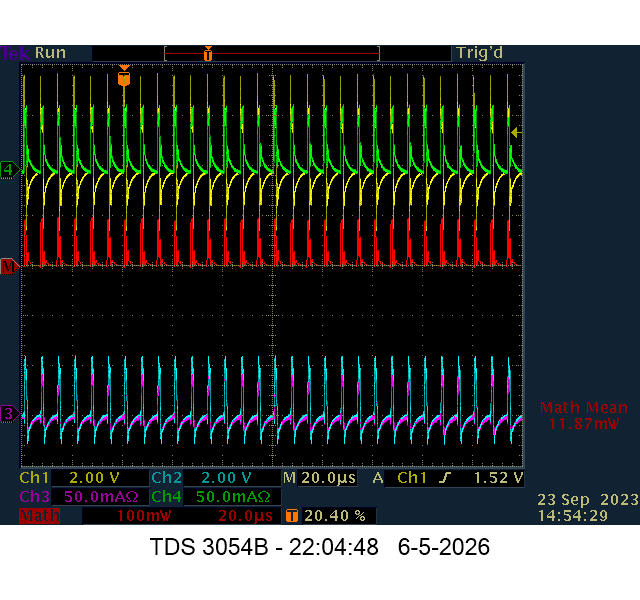


Output power multiple cycles


I rechecked by swapping the current probes and redo the above measurements which showed very similar results.

I will redo these measurements tomorrow again.

Itsu
   

Group: Moderator
Hero Member
*****

Posts: 2434
Please guide Itsu how to integrate these waveforms so the input and output energy can be compared.
Me thinks, he will need current waveforms, too.
I am not looking for OU in this pulse measurement as it is not the bucking coil arrangement.  However Itsu's new power measurements showing COPs of 1.07 and 1.13 are interesting and worthy of consideration.  If he repeated this measurement over reducing pulse widths and plotted COP against pulse width it might tell us something.  I note that in the 2019 work Itsu got some COP>1 results but when repeated the COP disappeared, so this latest result might follow that pattern.  If COPs>1 can be consistantly demonstrated to not be a measurement artifact this non-bucking approach is worthy of continued development.

Smudge
   

Group: Elite Experimentalist
Hero Member
*****

Posts: 4848

I agree, differences are very marginal, so further tests (swapping probes, using other methods like measuring primary and secondary separately to avoid ground loops, using different scope etc.) need to be done first.

Itsu


Group: Elite Experimentalist
Hero Member
*****

Posts: 4848
Today i was doing some extensive testing on the primary and secondary coils with regard to input and output power measurements.

There was a marginal difference between input and output in favor of output power using the older TDS-3054B scope using two P6139B voltage probes and 2 P6302 current probes.
Using one set of voltage and current probes (measuring the primary, then the secondary) and / or swapping the current probes over did not change this.

When i used the younger and more sophisticated MDO3054 scope with one voltage probe and one current probe measuring the primary, then the secondary showed something different.
There was hardly any difference in input and output power and the difference (0.3mW) was in favor of the input as one would expect in this circuit.

When on the TDS-3054B instead of the current probes using two 1 Ohm 1% induction free current sensor resistors at the primary input and secondary output, it was confirmed that there is slightly more power going in then coming out.     

The problem i think is that the TDS-3054B has a limited range of manual de-skewing (+10 to -10ns) a probe while the P6302 current probe is specified as having a skew of 30ns.
So setting the voltage probe to +10 and the current probe to -10 will leave a difference of 10ns.
Probably either the input or output is more prone to be influenced by this remaining 10ns skew which shows up in the positive result for the output power.

The MDO3054 has a preprogrammed list of probes and their delays and can be automatically set to compensate them, so they all are equal.

So, nothing unusual here IMO.

Itsu


Group: Moderator
Hero Member
*****

Posts: 2434
Thanks Itsu.  Back to the bucking coils test which is looking for some induced negative resistance when power is supplied to the connected coils.  This should show up when using sinewave input at a frequency associated with the tranmission line delay time.  I had suggested looking for a peak Q value at the appropriate frequency but you could instead look for a reduction in input power.  A plot of input power against frequency might show a dip at the right point.  Perhaps include a small load resistor in series with the coils so that you are measuring a serious quantity of power and not just circuit losses.

Smudge
   

Group: Elite Experimentalist
Hero Member
*****

Posts: 4848

Ok, i can do that, but you need to be more specific about "a small load resistor", like 50 Ohm?

Could this "small load resistor in series with the coils" be in between the 2 bucking coils?

There is NO capacitor (series or parallel) involved in the experiment, right?

Itsu
   
Pages: 1 2 3 4 [5] 6
« previous next »


Home Help Search Login Register
Theme © PopularFX | Based on PFX Ideas! | Scripts from iScript4u 2026-08-14, 21:52:04
