PopularFX
Home Help Search Login Register
Welcome,Guest. Please login or register.
2026-08-14, 21:53:26
News: A feature is available which provides a place all members can chat, either publicly or privately.
There is also a "Shout" feature on each page. Only available to members.

Pages: [1] 2 3 4 5 6 7
Author Topic: Q measurement methods  (Read 1577 times)

Group: Moderator
Hero Member
*****

Posts: 4848


This thread is opened to investigate the methods available to measure the Q of an LCR circuit.

Some information is already available in another thread, but to not further interrupt that thread this new one is opened.

That old thread information can be found starting from here: https://www.overunityresearch.com/index.php?topic=4927.msg118776#msg118776


Itsu
   

Group: Moderator
Hero Member
*****

Posts: 4848

The last information on that old thread was about measuring a T200-2 toroid which according this datasheet:  https://datasheets.micrometals.com/T200-2-DataSheet.pdf should be able to reach a (theoretical?) Q of 332:

Q test winding N=40, #20 AWG
Q frequency 2 MHz
Q min on HP4342A 332

I guess we could set that as a goal and try to come close to that figure.

Itsu
   

Group: Moderator
Hero Member
*****

Posts: 4848

A T200-2 toroid with 40 turns / 0.8mm diameter (#20 AWG) coil should have a parallel or series capacitance of 300pF to be resonant at 2MHz.

I will make such a resonator and do some initial (Fres / Bandwidth (-3dB) ) measurements to see where we stand using this simple method.

Itsu
   

Group: Moderator
Hero Member
*****

Posts: 4848

This is the device under test (DUT):


FG input through a single turn: ~2MHz at 20Vpp.

At resonance (2180kHz), output P6139 probe 10MOhm / 8pF see yellow trace, input blue trace:


Measuring the frequency at -3dB points (Fres x 0.707 = 26.159V)  gives High 2260kHz, low 2116kHz = difference of 144.
Q = Fres/difference = 2180 / 144 = 15.1, so a far cry of the theoretical Q of 332

Itsu
   
Group: Tech Wizard
Hero Member
*****

Posts: 1385
Hi Itsu,

Thanks for starting this topic.

I referred to this Amidon data sheet page 15 https://alexsradioshop.de/wp-content/uploads/2023/01/AmidonAMI.pdf  in the other thread.  It has graphs for the T200-2 core's Q values in the function of frequency and in the function of the number of turns.

From the graph, it is shown that to get Q > 300, the number of turns would be between roughly 25 and 40 (i.e. the coil inductance is between 8uH and 20 uH) in the frequency range between 3 MHz and 4 MHz. 
For the number of turns I would suggest using between 20 and 25 if the intended resonant frequency remains around 3.8 MHz, this gives coil inductance between 4.8 uH and 7.5 uH. So the tuning capacitor should be chosen accordingly. 

Just seen your first measurement.  First try to measure the Q for the same LC  (remove only the 1 turn coupling coil) in the test circuit you showed for the nanoVNA here https://www.overunityresearch.com/index.php?topic=4927.msg118906#msg118906   Try to use less than 10 pF coupling capacitors like 2 x 10 pF at both the input and output or less.

Gyula
   
Group: Tech Wizard
Hero Member
*****

Posts: 1385
Itsu,  from the scope shot I assume the blue trace shows the generator input voltage feeding the 1 turn coupling coil, is this so?

If yes, its peak to peak amplitude is about 1200 mV and dividing the 37.77 Vpp by this it gives a Q of around 31, twice of the Q of the 3 dB point method. 

Perhaps the coupling capacitor test will bring a better Q value, though probably not yet over 300.

Gyula
   

Group: Moderator
Hero Member
*****

Posts: 4848


Gyula,

Quote
Itsu,  from the scope shot I assume the blue trace shows the generator input voltage feeding the 1 turn coupling coil, is this so?

that is correct, i added the blue trace pp value (1.17Vpp) in that screenshot, and indeed this method yields a Q of 31.6.

I will use the nanoVNA method using the coupling capacitors.

I tested earlier with self-made dual bonded magnet wire caps trimmed to 1pF, but that gave a too marginal signal to show a reliable measurement, i will start with 2x 10pF in series (5pF)  at the in- and outputs.

Itsu


Group: Moderator
Hero Member
*****

Posts: 4848
Here i connected the DUT as shown using 3x 10pF (~4pF) caps in series at the in- and output of the nanoVNA:


The results are shown here but are kind of rough due to the low (4pF) coupling at the in and output of the nanoVNA:


But it shows again a Q of 15.3.


I will try to keep "score" from the different method at each measurement post:

Method 1: FG / Scope single loop coupling     Fres / bandwidth (-3dB):          Q = 15.1
Method 2: FG / Scope single loop coupling     Output Voltage / input voltage: Q = 31.6
Method 3: nanoVNA 4pF coupling in and out  Fres / bandwidth (-3dB):          Q = 15.3


Itsu
   
Group: Tech Wizard
Hero Member
*****

Posts: 1385
Ok Itsu,  thanks.

In this paper I have found, in the bottom part of page 9 there is info on using a (nano)VNA for measuring Q. https://w7zoi.net/oldtech/zoi-nano.pdf  No coupling caps are used, the series LC circuit shunts the TX-RX ports to ground that are connected together via an SMA Tee, the series LC makes a notch in the frequency response.
Then the author refers to a formula 7.4 in page 7.34 in this book, EMRFD which is Experimental Methodes in RF Design, see here https://www.scribd.com/document/336323413/Experimental-Methods-in-RF-Design 
We could try this and see what Q it gives.

Another method for Q measurement is the use of the 50:1 turns ratio transformer I already referred to in the other thread, https://www.overunityresearch.com/index.php?topic=4927.msg118917#msg118917  using the T520-2 with the 50 turns for primary and a single turn for the secondary coils. 

Here is another very good paper based (also) on measurements which includes the Q of several capacitor types https://w7zoi.net/twofaces.pdf 

Of course, these need time to digest and decide on the test circuit, no need for any hurry.

Gyula


Group: Administrator
Hero Member
*****

Posts: 4856
This thread is opened to investigate the methods available to measure the Q of an LCR circuit.
My 2 cents so you don't feel abandoned.
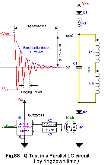


Measure the current in the yellow wire using your contactless current probe.
Keep the yellow wires thick and short.

Make the R1 resistance such that the maximum current flowing through the MOSFET and D1 and D2 approaches their current ratings (imax) but does not exceed them ( R1≈VCC/imax )
Keep the R2 gate resistor high and R3 gate resistor low resistance (as low as it is safe).

Once the Q2 MOSFET turns OFF, the LC tank becomes isolated and can ring down with minimal loading (which is the resistance of R1 combined with the reactance of MOSFTET's output capacitance COSS in series with the reverse capacitances of D1 and D2,  CTOTAL=CD1CD2COSS/[CD1CD2+CD1COSS+C2COSS] ).
The MOSFET's VD-S_max and the D1 and D2 blocking voltage should be at least 2*VCC.  The D1 and D2 should have a small junction capacitance under reverse biased conditions. ...the MOSFET's Coss should be as small as possible, too (this capacitance decreases as the drain voltage increases).  Ferrite beads on D1 and D2 might decrease the loading further (worth trying with and without them).

CALCULATIONS:
The time to ring down to 50% of the initial amplitude and multiplied by π/ln2 (4.53236...) and divided by the ringing period is the Quality Factor (Q).
The time to ring down to 37% of the initial amplitude and multiplied by π (3.14159...) and divided by the ringing period is the Quality Factor (Q), too.
The time to ring down to 4.32% of the initial amplitude divided by the ringing period is the Quality Factor (Q), too.

   
Group: Tech Wizard
Hero Member
*****

Posts: 1385
Verpies,  would you tell Itsu whether he use the series aiding or bucking connection for the two coils?  (The two dots show series aiding, of course.)

Gyula
   

Group: Administrator
Hero Member
*****

Posts: 4856
Verpies,  would you tell Itsu whether he use the series aiding or bucking connection for the two coils?  (The two dots show series aiding, of course.)
He sometimes uses aiding and sometimes bucking and compares them.
   

Group: Moderator
Hero Member
*****

Posts: 4848
Ok Itsu,  thanks.

In this paper I have found, in the bottom part of page 9 there is info on using a (nano)VNA for measuring Q. https://w7zoi.net/oldtech/zoi-nano.pdf  No coupling caps are used, the series LC circuit shunts the TX-RX ports to ground that are connected together via an SMA Tee, the series LC makes a notch in the frequency response.
Then the author refers to a formula 7.4 in page 7.34 in this book, EMRFD which is Experimental Methodes in RF Design, see here https://www.scribd.com/document/336323413/Experimental-Methods-in-RF-Design 
We could try this and see what Q it gives.

Another method for Q measurement is the use of the 50:1 turns ratio transformer I already referred to in the other thread, https://www.overunityresearch.com/index.php?topic=4927.msg118917#msg118917  using the T520-2 with the 50 turns for primary and a single turn for the secondary coils. 

Here is another very good paper based (also) on measurements which includes the Q of several capacitor types https://w7zoi.net/twofaces.pdf 

Of course, these need time to digest and decide on the test circuit, no need for any hurry.

Gyula


Thanks Gyula,   good finds, i will study the first one first (nanoVNA).

Itsu
   

Group: Moderator
Hero Member
*****

Posts: 4848
My 2 cents so you don't feel abandoned.


Measure the current in the yellow wire using your contactless current probe.
Keep the yellow wires thick and short.

Make the R1 resistance such that the maximum current flowing through the MOSFET and D1 and D2 approaches their current ratings (imax) but does not exceed them ( R1≈VCC/imax )
Keep the R2 gate resistor high and R3 gate resistor low resistance (as low as it is safe).

Once the Q2 MOSFET turns OFF, the LC tank becomes isolated and can ring down with minimal loading (which is the resistance of R1 combined with the reactance of MOSFTET's output capacitance COSS in series with the reverse capacitances of D1 and D2,  CTOTAL=CD1CD2COSS/[CD1CD2+CD1COSS+C2COSS] ).
The MOSFET's VD-S_max and the D1 and D2 blocking voltage should be at least 2*VCC.  The D1 and D2 should have a small junction capacitance under reverse biased conditions. ...the MOSFET's Coss should be as small as possible, too (this capacitance decreases as the drain voltage increases).  Ferrite beads on D1 and D2 might decrease the loading further (worth trying with and without them).

CALCULATIONS:
The time to ring down to 50% of the initial amplitude and multiplied by π/ln2 (4.53236...) and divided by the ringing period is the Quality Factor (Q).
The time to ring down to 37% of the initial amplitude and multiplied by π (3.14159...) and divided by the ringing period is the Quality Factor (Q), too.
The time to ring down to 4.32% of the initial amplitude divided by the ringing period is the Quality Factor (Q), too.

Verpies,   Thanks, I feel better now  ;)


I did use the ringing method on Smudge's device, but very simple, like pulsing with a short pulse from the FG via a single loop, scope the ringing output and count the cycles to half the amplitude etc.
It turned out to match the Fres / bandwidth method Q value.

But using the contactless current probe to measure the ringing omits the scope probe loading  O0

So i will try that too.

In this DUT (T200-2) we only have 1 coil in the LCR circuit, so no aiding or bucking modes available.

Itsu
   

Group: Administrator
Hero Member
*****

Posts: 4856
In this paper I have found, in the bottom part of page 9 there is info on using a (nano)VNA for measuring Q. https://w7zoi.net/oldtech/zoi-nano.pdf  No coupling caps are used, the series LC circuit shunts the TX-RX ports to ground that are connected together via an SMA Tee, the series LC makes a notch in the frequency response.

That would be the measurement #2.

Let's keep this organized - there are four S21 measurement possible:
1) Shunt-through S21 measurement of a parallel LC DUT
2) Shunt-through S21 measurement of a series LC DUT
3) Series S21 measurement of a parallel LC DUT
4) Series S21 measurement of a series LC DUT


I did use the 2) Shunt-through S21 measurement of a series LC DUT in the measurement shown.

Measurement #3 would make sense, too.
   

Group: Moderator
Hero Member
*****

Posts: 4848
My 2 cents so you don't feel abandoned.


Measure the current in the yellow wire using your contactless current probe.
Keep the yellow wires thick and short.

Make the R1 resistance such that the maximum current flowing through the MOSFET and D1 and D2 approaches their current ratings (imax) but does not exceed them ( R1≈VCC/imax )
Keep the R2 gate resistor high and R3 gate resistor low resistance (as low as it is safe).

Once the Q2 MOSFET turns OFF, the LC tank becomes isolated and can ring down with minimal loading (which is the resistance of R1 combined with the reactance of MOSFTET's output capacitance COSS in series with the reverse capacitances of D1 and D2,  CTOTAL=CD1CD2COSS/[CD1CD2+CD1COSS+C2COSS] ).
The MOSFET's VD-S_max and the D1 and D2 blocking voltage should be at least 2*VCC.  The D1 and D2 should have a small junction capacitance under reverse biased conditions. ...the MOSFET's Coss should be as small as possible, too (this capacitance decreases as the drain voltage increases).  Ferrite beads on D1 and D2 might decrease the loading further (worth trying with and without them).

CALCULATIONS:
The time to ring down to 50% of the initial amplitude and multiplied by π/ln2 (4.53236...) and divided by the ringing period is the Quality Factor (Q).
The time to ring down to 37% of the initial amplitude and multiplied by π (3.14159...) and divided by the ringing period is the Quality Factor (Q), too.
The time to ring down to 4.32% of the initial amplitude divided by the ringing period is the Quality Factor (Q), too.

Initial test run using the above shown method and this calculation: "The time to ring down to 4.32% of the initial amplitude divided by the ringing period is the Quality Factor (Q), too".

These are the components i used and the results in green:


Here the screenshot from the current ringdown in green (blue is input pulse from FG):


Q calculates as 19 if i understand the calculations correctly.

Edit:  D1 is also a 1N4148 (100V / 300mA and junction capacitance of 4pF).
         Coss of the MOSFET is 185pF
Itsu
   

Group: Administrator
Hero Member
*****

Posts: 4856
Q calculates as 19 if i understand the calculations correctly.

Edit:  D1 is also a 1N4148 (100V / 300mA and junction capacitance of 4pF).
         Coss of the MOSFET is 185pF
Looks correct.  I count a little more than 19 ringing cycles to your cursor, though.

The major improvement would be to install low-capacitance low-voltage TVS diodes (like SP0402B-ULC) in place of D1 and D2 and increasing VCC by their combined voltage drop.
Another and smaller improvement would be to use a MOSFET with a lower COSS.  Most likely a higher voltage MOSFET or GaN like EPC2037. 
imax of present D1 and D2 limit you to 300mA anyway (a big mismatch with the 14A IDmax of the present Q2).

Cosmetically, I'd increase R2 a lot to minimize ringing and maximize stability when Q2 turns ON.

QUESTION: What is the capacitance of your low-voltage bidir-TVS diodes ?
With low-capacitance TVS diodes like SP0402B-ULC you could decrease the LC tank loading 100x
   

Group: Moderator
Hero Member
*****

Posts: 4848
My 1.5KE18CA bidi TVS (18V) seem to have a capacitance between 2 and 4.3nF, so not really an option and compared to your SP0402B-ULC a nono.

The RFD14N05L was the MOSFET with the lowest Coss i had available, other MOSFETs including higher voltage ones like IRF740 / IRF840 and IRFP460 etc. all had higher (330pF) values.

Would changing those components you suggested make such a difference that it would near the (theoretical?) Q 0f 300 as specified in the T200-2 toroid datasheet?

Itsu


Group: Administrator
Hero Member
*****

Posts: 4856
Would changing those components you suggested make such a difference that it would near the (theoretical?) Q 0f 300 as specified in the T200-2 toroid datasheet?
I don't know.
The SP0402B-ULC diodes would decrease the LC loading not only by their lower capacitance but also by blocking conduction in both directions below their combined breakdown voltage (2*9V). 
With these diodes, the LC tank could ring freely below ±18Vp-p amplitude while being loaded down by a reactance of less than 0.13pF
   

Group: Moderator
Hero Member
*****

Posts: 4848
Ok,  good enough for me, i will order those TVS's and some EPC2037's.

Meanwhile i will proceed with the other mentioned methods.
   

Group: Moderator
Hero Member
*****

Posts: 4848
Next i used the method mentioned by Gyula in an earlier post:

Quote
In this paper I have found, in the bottom part of page 9 there is info on using a (nano)VNA for measuring Q. https://w7zoi.net/oldtech/zoi-nano.pdf  No coupling caps are used, the series LC circuit shunts the TX-RX ports to ground that are connected together via an SMA Tee, the series LC makes a notch in the frequency response.
Then the author refers to a formula 7.4 in page 7.34 in this book, EMRFD which is Experimental Methods in RF Design, see here https://www.scribd.com/document/336323413/Experimental-Methods-in-RF-Design
We could try this and see what Q it gives.

The suggested nanoVNA and DUT setup looks like this:


The formula mentioned in the book 7.4 in page 7.34 look like this:


So after setting it up the nanoVNA produced this result:


Using the shown formula (i used the series LC setup Qs) where f = 2.239MHz, A = -7.1dB, Lu = 19uH and Z =50 Ohm, i calculated Q to be 13.46  (please check my result).


Again very close to the earlier used methods results.


"score" from the different method at each measurement post:

Method 1: FG / Scope single loop coupling     Output Voltage / input voltage: Q = 31.6
Method 2: FG / Scope single loop coupling     Fres / bandwidth (-3dB):          Q = 15.1
Method 3: nanoVNA 4pF coupling in and out  Fres / bandwidth (-3dB):          Q = 15.3
Method 4: verpies his current probe ringdown setup                                     Q = 19
Method 5: FG / Scope 3pF coupling in and out Fres / bandwidth (-3dB)          Q = 15.25    (i also tried with ONLY 1pF capacitor as input, result was Q = 15.8 )
Method 6: nanoVNA Tee setup / formula used                                              Q = 13.46

Itsu 
   

Group: Administrator
Hero Member
*****

Posts: 4856
So after setting it up the nanoVNA produced this result:

That's a very handsome notch.

Method 1: FG / Scope single loop coupling     Output Voltage / input voltage: Q = 31.6
Method 2: FG / Scope single loop coupling     Fres / bandwidth (-3dB):          Q = 15.1
Method 3: nanoVNA 4pF coupling in and out  Fres / bandwidth (-3dB):          Q = 15.3
Method 4: verpies his current probe ringdown setup                                     Q = 19
Method 5: FG / Scope 3pF coupling in and out Fres / bandwidth (-3dB)          Q = 15.25    (i also tried with ONLY 1pF capacitor as input, result was Q = 15.8 )
Method 6: nanoVNA Tee setup / formula used                                              Q = 13.46

The average of these 6 measurements is 18.285
   

Group: Administrator
Hero Member
*****

Posts: 4856
Ok,  good enough for me, i will order those TVS's and some EPC2037's.
EPC2038 is the lowest COSS (1.6pF) MOSFET but it can handle only 500mA of pulsed current.

EPC2037 has a 6.5pF COSS but it can handle 2.4A, which is similar to the 2A imax of the SP0402B-ULC TVS diode.
EPC8010 can handle 7.5A at the expense of 25pF COSS.
EPC2036 can handle 18A at the expense of 50pF COSS.
All of the above are 100V MOSFETs. 

A noteworthy 200V MOSFET is the EPC2012C which can handle 22A at 64pF COSS.


Group: Moderator
Hero Member
*****

Posts: 4848

Thanks, i ordered some of these parts.


Meanwhile Gyula was still wondering why the Q results are so low (around 15), and in a simulation he showed that a high ESR of the resonance capacitor (287pF) could cause this.

Using my Agilent 1733C LCR meter which has buttons for ESR and DCR measurements showed that the 287pF resonance capacitor had an ESR of 83 Ohm.

Looking at the datasheet of that TDK 100pF ceramic capacitor (i use 3 parallel) it turns out that that is according to its specs:


I don't think this causes a problem to see which method is the better one as they all measure the same thing, but it could explain why we see such a low Q.

Itsu


Group: Administrator
Hero Member
*****

Posts: 4856
Using my Agilent 1733C LCR meter which has buttons for ESR and DCR measurements showed that the 287pF resonance capacitor had an ESR of 83 Ohm.
So add a low-ESR cap to your parts order before it ships on Monday.
I have been pretty happy with Murata ERB series capacitors that have 40mΩ ESR at 3MHz.
   
Pages: [1] 2 3 4 5 6 7
« previous next »


Home Help Search Login Register
Theme © PopularFX | Based on PFX Ideas! | Scripts from iScript4u 2026-08-14, 21:53:26