PopularFX
Home Help Search Login Register
Welcome,Guest. Please login or register.
2026-08-14, 21:55:13
News: Check out the Benches; a place for people to moderate their own thread and document their builds and data.
If you would like your own Bench, please PM an Admin.
Most Benches are visible only to members.

Pages: 1 2 [3] 4 5 6
Author Topic: Bucking Coils  (Read 2307 times)

Group: Elite Experimentalist
Hero Member
*****

Posts: 4848
Gyula,

I had the 2N3055 too good isolated from its heat sink, so good that also the 12V was isolated from the collector  :-[


Anyway, running with the 2N3055 alone, using first 1K for R1 (7.5V across Re), then 470 Ohm for R1 (8.6V across Re, so better), but neither was able to produce output across the 100pF capacitor (800mVpp in, 800mVpp out).
No matter how i cranked up the FG signal (it seems to be clamped to 800mVpp).


When including the 2N2222 (darlington style), R1 to 100K, still at 12V input i get a distorted signal at the base of the 2N3055 and almost no output of the 2N3055.
I have to crank up the FG input lot to see this output jump up and at the same time see the voltage across Re jump to 10V, but the output is way to low, see screenshot.

Blue is distorted base signal of the 2N3055, yellow the signal across the 100pF cap.


LTspice sim added how i have it configured right now.

Itsu
   
Group: Tech Wizard
Hero Member
*****

Posts: 1385
Thanks.  Try to put a few kOhm (1, 2.2 3.3) resistor across the base and emitter of the 2N3055. Without the LC circuit across the emitter resistor, try to achieve a normal operation i.e. a correct sine wave across the 10 Ohm (while the DC voltage is around 8 - 9 V at least) for the Darlington emitter follower like you had with the single 2N2222.  Maybe with other power transistor like BD139 or TIP31 etc you may get better results.  Though their transition frequency is around 3-4 MHz too. 

Gyula
   
Group: Tech Wizard
Hero Member
*****

Posts: 1385
Just thought of LTSpice...   :)    will play with it, thanks for the circuit file.
   
Group: Tech Wizard
Hero Member
*****

Posts: 1385
The resonant frequency of the 100 pF - 16.7 uH is 3894.6 kHz, I modified it in the asc file, attached.  I run the simulation with 20 V DC instead of the 12 V, the AC emitter voltage seems improving.
See the attached asc file.  Try to run the breadboarded circuit from 20 V (or vary the level) of the PS. (The emitter resistor has around 1 A and 10 V now in the simulator)
Will be back tomorrow evening.

Edit,  I assume that due to L and C component tolerances, the slightly differing resonant frequency is not an issue because you fine tune the signal generator for maximum peak to peak voltage across the 100 pF and the probe's capacitance may pull the frequency down a little.

Gyula
   

Group: Elite Experimentalist
Hero Member
*****

Posts: 4848
Gyula,

Thanks for the info, i will play around with the input voltage.

I see you also changed over the R1 and R2 resistors (from your original posted circuit in post #30) R1 is now 33K and R2 is 100K.

One question: how to measure the Q in the "darlington situation"?

Do we still use the "the input voltage of the signal generator driving the base" and if yes, which base? (the 2N2222 base, the 2N3055 base or the FG voltage itself).

If i use the 2N2222 base voltage signal (in your simulation) i have 11.0 to 12.1 = 1.1Vpp and have an output resonance voltage across the 100pF capacitor of 7.05 to 14 = 7Vpp meaning a Q of 7 / 1.1 =  6.36.


Is this the correct way?

Itsu
« Last Edit: 2026-04-16, 15:33:38 by Itsu »
   
Group: Tech Wizard
Hero Member
*****

Posts: 1385
Hi Itsu,

I corrected a little the circuit to have a better response, see the attached asc file. I reduced the signal generator output voltage to 10mV (at f=3868 kHz), I chose the
series DC resistance of L1 to be 0.1 Ohm what you measured with the Ohm meter, I chose the ESR of the 100 pF capacitor also to 0.1 Ohm (a good quality capacitor should have
an ESR < 0.1 Ohm).
Note that with 500 mV generator input the resonant frequency of L1C2 also changes, this change can be considered normal I think, driving voltage levels change
semiconductor parameters.
Note also: if we choose 100 mV input for the generator, the resonant frequency changes to 3878 kHz to get maximum resonant voltage across either L1 or C2
as per the simulator.

Regarding where to measure the generator voltage: I think across the 10 Ohm emitter resistor and the scope be in AC coupling to get rid of the DC component.
OR try to measure directly across L1 with 2 probes in differential mode (probes alligator clips floating).

Here is the simulator display of the voltage across the 10 Ohm, (1st pic), the AC wave rides about on 10.312 VDC, if I use the cursor for this V(n003) AC voltage and I
substract the bottom peak value from the top peak value, I get 10.314413 - 10.311302 = 3.111 mV, (this seems to remain from the 10 mV generator input). I blew up the
display for the V(n003) AC emitter voltage vertically for clarity, cursor shows the bottom peak value (riding on the DC value) which is 10.311302.

The 2nd picture (blown up horizontally) shows the direct generator input voltage (20 mVpp in red color) and the voltage across the L1 coil (3.79 Vpp in green color).
So the Q of the L1 coil would be 3790 mV / 20 mV = 189.5 and considering the same ESR of 0.1 Ohm I used in the simulation for the 100 pF, we would need to halve this,
getting about Q = 94.7 for the LC circuit WHEN we use the direct generator input voltage.

Using the AC emitter voltage which is only 3.111 mVpp in this simulation, the calculated Q would be higher, i.e. 3790 mV / 3.111 mV =  1218 and halving this would give
Q = 609
Considering the inductive reactance of L1 which is around XL1 = 406 Ohm at 3868 kHz and considering its 0.1 Ohm DC resistance, the calculated Q from these data would be
Q = 406 / 0.1 = 4060 in theory. The core loss and the virtual emitter resistance surely reduces the real Q and it should be (much) higher than 7 to 11 or so values.
Hopefully the measurements would reveal this.

Gyula
   

Group: Administrator
Hero Member
*****

Posts: 4856
Can the 2N3055 handle 3868kHz in this configuration ?
Does LTSpice have its precise model or is it just using a generic or ideal BJT model ?
   
Group: Tech Wizard
Hero Member
*****

Posts: 1385
Surely the 3.8 MHz is little high for the data sheet's 2.5 MHz fT where the small signal current gain (hfe) of the transistor has a magnitude of 1. I suspected
this can be a drawback in the tests and the next step would be to replace this type with a better one.
LTSpice has transistor models given by manufacturers, for each type the component library includes. The 2N3055 model came from ST Microelectronics. Probably they did their best to fit their model to a real 2N3055 as close as possible as most manufacturers did. 
   
Group: Tech Wizard
Hero Member
*****

Posts: 1385
Itsu, if you have for instance BD135, BD137 or BD139 for instance, these have 40 -50 MHz  or higher transition frequencies, depending on manufacturers. 
Or if you have some other power types in junk box, consult their data sheet.  1.5 Amper max collector current is already enough with the fT of 40-50 MHz.

EDIT  it is possible that no Darlington config is needed with the above types.

Gyula
   

Group: Elite Experimentalist
Hero Member
*****

Posts: 4848
Hi Itsu,

I corrected a little the circuit to have a better response, see the attached asc file. I reduced the signal generator output voltage to 10mV (at f=3868 kHz), I chose the
series DC resistance of L1 to be 0.1 Ohm what you measured with the Ohm meter, I chose the ESR of the 100 pF capacitor also to 0.1 Ohm (a good quality capacitor should have
an ESR < 0.1 Ohm).
Note that with 500 mV generator input the resonant frequency of L1C2 also changes, this change can be considered normal I think, driving voltage levels change
semiconductor parameters.
Note also: if we choose 100 mV input for the generator, the resonant frequency changes to 3878 kHz to get maximum resonant voltage across either L1 or C2
as per the simulator.

Regarding where to measure the generator voltage: I think across the 10 Ohm emitter resistor and the scope be in AC coupling to get rid of the DC component.
OR try to measure directly across L1 with 2 probes in differential mode (probes alligator clips floating).

Here is the simulator display of the voltage across the 10 Ohm, (1st pic), the AC wave rides about on 10.312 VDC, if I use the cursor for this V(n003) AC voltage and I
substract the bottom peak value from the top peak value, I get 10.314413 - 10.311302 = 3.111 mV, (this seems to remain from the 10 mV generator input). I blew up the
display for the V(n003) AC emitter voltage vertically for clarity, cursor shows the bottom peak value (riding on the DC value) which is 10.311302.

The 2nd picture (blown up horizontally) shows the direct generator input voltage (20 mVpp in red color) and the voltage across the L1 coil (3.79 Vpp in green color).
So the Q of the L1 coil would be 3790 mV / 20 mV = 189.5 and considering the same ESR of 0.1 Ohm I used in the simulation for the 100 pF, we would need to halve this,
getting about Q = 94.7 for the LC circuit WHEN we use the direct generator input voltage.

Using the AC emitter voltage which is only 3.111 mVpp in this simulation, the calculated Q would be higher, i.e. 3790 mV / 3.111 mV =  1218 and halving this would give
Q = 609
Considering the inductive reactance of L1 which is around XL1 = 406 Ohm at 3868 kHz and considering its 0.1 Ohm DC resistance, the calculated Q from these data would be
Q = 406 / 0.1 = 4060 in theory. The core loss and the virtual emitter resistance surely reduces the real Q and it should be (much) higher than 7 to 11 or so values.
Hopefully the measurements would reveal this.

Gyula


Gyula,

Thanks for the info.

What strikes my from the start is that you are able to produce 3 different Q values on this one circuit depending on how / where you measure:  Q = 94.7, Q = 609 and Q = 4060.
This sound very odd to me.

Anyway, i can reproduce your values in the sim, but when i try it on my real circuit, things are very different.

Firstly, the 10mV (20mVpp) input from the FG is so low, my scope has problems showing it, see the blue trace (23.7mVpp) in the screenshot below.

But also this low input voltage seems problematic for the rest of the circuit as the voltage across the 100pF capacitor is still very low (274mVpp, see yellow trace).
When using my differential probe across the coil L1, it not only influences the resonance frequency (3620kHz), but it also shows a low value as 285mVpp, see purple trace:
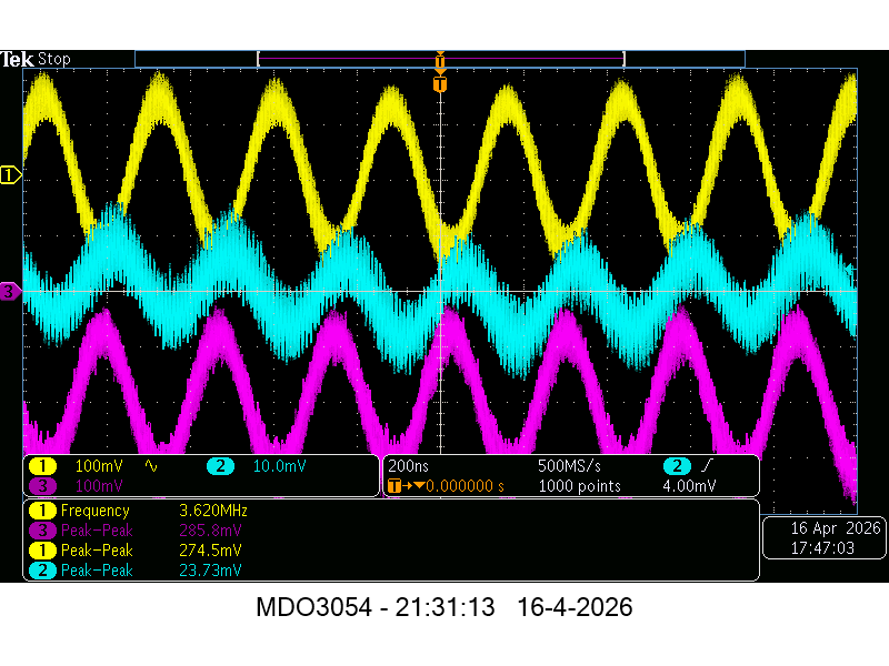


In this situation with 20V input, there is 1.12A running through my 10.4 Ohm emitter resistor which get hot quick.

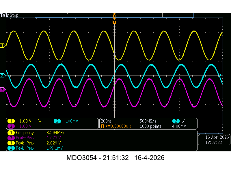
I have to increase the FG input to at least 150mVpp to get some readable signals, but still the Q will be around the familiar level of 11:


Further increase of the input (500mVpp) lowers again the Q, see here:
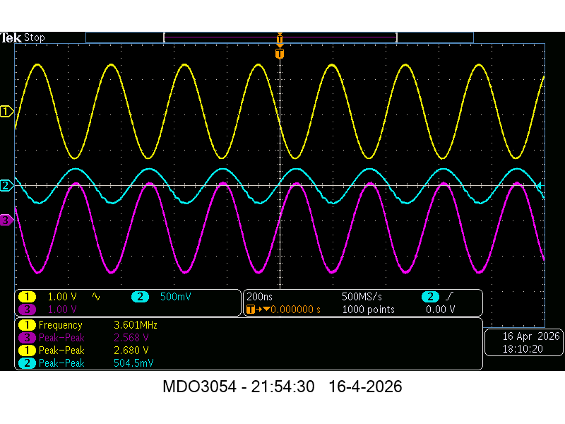


I indeed think the 2N3055 has problems with the used frequency, and also the probes seem to have again an impact on the Q as well.

I will see what i have in the junk box, would 2SC5200 do?  I have some.


Itsu

   
Group: Tech Wizard
Hero Member
*****

Posts: 1385
Ok Itsu, and thanks for your efforts.  Sorry that I did not consider the frequency specs of the 2N3055. 

IF you use the Darlington config with another power transistor, use a 220 kOhm trimmer or normal potmeter for R2, this would help find better bias points. 
In the BD 135 etc family the types are marked with A, B and C in the suffix (if you happen find such) meaning the types are sorted for hFE, C meaning the highest (over 150 - 200).

Always fine tune the generator frequency for resonance whenever you change something, as so far you surely did so.   8)   

Gyula


Group: Elite Experimentalist
Hero Member
*****

Posts: 4848
Gyula,  i have some 2SC5200, with a hFE of 55 and an fT of 30Mhz, i will try one tomorrow.

Itsu
« Last Edit: 2026-04-17, 09:42:28 by Itsu »
   
Group: Tech Wizard
Hero Member
*****

Posts: 1385
You mean 2SC5200 rather than 2SD5200 ?   Is it made by Toshiba?

I cannot find 2SD5200 data sheet.
   

Group: Administrator
Hero Member
*****

Posts: 4856
In this situation with 20V input, there is 1.12A running through my 10.4 Ohm emitter resistor which get hot quick.
Are your EL2009 buffers stable at such currents ?
   

Group: Elite Experimentalist
Hero Member
*****

Posts: 4848
Gyula, 

sorry, yes the 2SC5200 from Toshiba


verpies,

i am using my FY8300 FG for such experimental measurements, its cheaper to replace  :)


An initial test with the 2SC5200 looks better, but i just soldered the 2SC5200 in place of the 2N3055 without changing something else.
I have 214mVpp in from the FG and 5.5Vpp out across the 100pF cap pointing to a Q of 25 (differential probe across L1 removed).

I will use a 220K trimmer for R2 and look for a sweet spot later on today.

Itsu
   

Group: Elite Experimentalist
Hero Member
*****

Posts: 4848


Gyula,

i installed a 220K trimmer pot as R2 (2N2222 base to ground) and played around with the input voltage, input signal from FG and trimmer setting while keeping peak resonance.

It boils down to a max. reachable Q of 25.9.

The input voltage is 20V, the current through the 10.4 Ohm emitter resistor is 1.38A, the trimmer pot is set to 213KOhm and the input signal from the FG is 280mVpp (blue trace).
This results in a resonance voltage across the 100pF capacitor of 7.2V (yellow trace), with a slightly distorted input signal, see screenshot:


Itsu
   
Group: Tech Wizard
Hero Member
*****

Posts: 1385
Hi Itsu,

Many thanks. 

Because the AC voltage is surely less across the 10 Ohm than the AC input from the generator, this means the Q is higher than 25.9 (the 7.2V then is divided by a less than 280 mV value).

(Small note if I may: Probably you may have connected the 220 k trimmer between the base of the 2N2222 and the positive rail.) 

The LTSpice includes transistor 2SC5200 with a suffix of letter O, so the hFE ranges between 80 to 160, https://www.farnell.com/datasheets/316951.pdf   I will use it in simulation without a Darlington config first.

Good night,
Gyula
   

Group: Elite Experimentalist
Hero Member
*****

Posts: 4848

Gyula,

i can make an AC measurement across the 10 Ohm resistor later today.

Not sure what you mean by your "Small note...", as i had mentioned that i have connected the 220K trimmer from base (2N2222) to ground, so do you mean i can try to put it between base (2N2222) and the positive rail?

Itsu
   
Group: Tech Wizard
Hero Member
*****

Posts: 1385
Hi Itsu,

I referred to this you wrote above: i installed a 220K trimmer pot as R2 (2N2222 base to ground)   In the simulation circuit drawing R2 is connected between the base of the 2N2222 and the positive rail, see Reply #55 what I mean:
 https://www.overunityresearch.com/index.php?topic=4927.msg118871#msg118871   This is what I wanted to clarify: I had thought R2 labeled as in the schematic, that is all.

EDIT 1  You may have meant R3 for using trimpot, not R2 ?  If yes, just let R3 remain a normal 100 k resistor and indeed connect the trimpot to replace R2 33 k resistor.  This may give a wider bias point adjustment possibility.
EDIT 2  Would you use another 100 pF capacitor instead of the present one?  Just for closing out unwanted surprises.

Gyula
« Last Edit: 2026-04-18, 12:02:32 by gyula »
   

Group: Elite Experimentalist
Hero Member
*****

Posts: 4848
Gyula,

All my references to the resistors R1, R2 etc. are to the original schematic you presented in your post #30 (even when using the darlington setup):


So my 220K trimmer pot is now R2, meaning in place of the original 33KOhm resistor.

To make it even more complicated, my R1 is now 33K due to a swap you made in your simulator which i had followed  :D


Quote
Because the AC voltage is surely less across the 10 Ohm than the AC input from the generator, this means the Q is higher than 25.9 (the 7.2V then is divided by a less than 280 mV value).

I made a new screenshot, with the FG output signal (now 310mVpp after cold startup), in white, and in blue the AC voltage across the 10.4 Ohm emitter resistor, while in yellow we still have the voltage in resonance across the 100pF capacitor:


I used another 100pF which measures the same as the old one.

When using the white trace (FG) as input, the Q = 26.8,  when i use the blue trace (across Re), the Q = 9.9

By the way, my real 2SC5200 reads: 2SC5200-O

Itsu
   
Group: Tech Wizard
Hero Member
*****

Posts: 1385
Hi Itsu,

I see.  Well, from the single 2N2222 schematic we changed to the Darlington configuration and I thought we are on the same page in component labels since then.   :D   No problem.

In the screenshot,  I do not understand how the AC voltage (836 mVpp) can be way higher across the (10 Ohm) emitter resistor versus the direct generator input of 310 mVpp?

A single emitter follower amplifies say 0.9 and a double emitter follower also, together 0.9 x 0.9 = 0.81   so a generator input of 310 mVpp should be around 0.81 x 310 = 251 mVpp.

Gyula
   
Group: Tech Wizard
Hero Member
*****

Posts: 1385
Itsu,

I simulated the series LC circuit alone, driven from a voltage generator via a 14.7 Ohm resistor, see the attached circuit. The generator has 0.1 Ohm internal resistance,
the coil and the capacitor are the same 16.7 uH, 0.1 Ohm and 100 pF ESR 0.1 Ohm.
With these component values the simulator gives the same screen shot you showed in your Reply #65   https://www.overunityresearch.com/index.php?topic=4927.msg118886#msg118886
Generator voltage in the simulator 140 mVp (which gives the 280 mVpp you had) and the AC voltage across the 100 pF is 7.24 Vpp, resonant frequency is 3894.6 kHz.

So the question now is what introduces the loss in the Darlington circuit you tested and took the referenced screen shot from? This loss is equivalent to a 14.7 Ohm resistor
in series with the LC circuit, I arrived at this resistor value by trial and error to get the 7.2 Vpp voltage across the 100 pF.

This loss IMHO cannot come from the Darlington circuit because the 10 Ohm emitter resistor is shunted by the virtual emitter resistor
which is rE = 26 mV / IE     so even an emitter current of say 10 mA causes rE to be 2.6 Ohm and this would shunt the actual emitter resistor (which is 10 Ohm here).

A possible loss factor might be the ferrite ring core, this is a guess of course. Maybe you have an Amidon soft powder ring core labeled as T56-  or higher OD, you could wind a 16-17 uH coil and see
how it behaves in the circuit.

Gyula
   

Group: Elite Experimentalist
Hero Member
*****

Posts: 4848


Gyula,
 
i have rewired the part from the 2SC5200 in with solid wire and soldering connections as there were clip leads there, but it did not make a change.

I still have the bigger AC voltage across the 10 Ohm emitter resistor compared to the FG input voltage so i cannot find any losses in that last path.

So it could be the ferrite.

Anyway, i was looking for an Amidon T56 toroid, but they seem to be non-existing, are you sure they exist?

I do have some others like (from small to big): T106-2, T200-2, T225-6-1 and T520-2
 
Itsu
   
Group: Tech Wizard
Hero Member
*****

Posts: 1385
Itsu,  the Amidon T50-6 core type was in my mind but I 'managed' to write T56-   sorry. 

Regarding the higher AC amplitude across the 10 Ohm, maybe the Darlington circuit regenerates, oscillates, I do not know. Try to reduce the 20 V supply voltage, this maybe a remedy.

May I refer to your single transistor test with the 2N2222 in your Reply #46 https://www.overunityresearch.com/index.php?topic=4927.msg118821#msg118821
where the generator input was 526 mVpp and across the emitter resistor the amplitude was 518 mVpp what you measured, this is the normal operation for an emitter follower.

Regarding your available Amidon cores, choose perhaps the T200-2 type, see Pages 3 and 15 in this data sheet https://alexsradioshop.de/wp-content/uploads/2023/01/AmidonAMI.pdf  The AL is 120 (uH/100 turns)
so to have 16.7 uH on this core the number of turns would be around 37.  Perhaps use the same kind of Litz wire for this coil but a normal enamelled copper wire would also do it (and easier to solder), say use around OD = 0.3 mm wire.

Gyula
   

Group: Elite Experimentalist
Hero Member
*****

Posts: 4848


Gyula,


Quote
May I refer to your single transistor test with the 2N2222 in your Reply #46 https://www.overunityresearch.com/index.php?topic=4927.msg118821#msg118821
where the generator input was 526 mVpp and across the emitter resistor the amplitude was 518 mVpp what you measured, this is the normal operation for an emitter follower.

Yes, i see what you mean.

Quote
Regarding your available Amidon cores, choose perhaps the T200-2 type, see Pages 3 and 15 in this data sheet https://alexsradioshop.de/wp-content/uploads/2023/01/AmidonAMI.pdf  The AL is 120 (uH/100 turns)
so to have 16.7 uH on this core the number of turns would be around 37.  Perhaps use the same kind of Litz wire for this coil but a normal enamelled copper wire would also do it (and easier to solder), say use around OD = 0.3 mm wire.

I had one T200-2 with 40 turns of 1mm diameter magnet wire lying around, so i removed some turns and at 37 turns i got an inductance of 16.8uH, so i used that.
This was the result without any other changes since yesterday, so still at 20V with 1A through the 10.4 Ohm emitter resistor:


Yellow is the output across the 100pF capacitor
Blue is the input from the FG (set at 280mVpp)
White is the AC voltage across the 10.4 Ohm emitter resistor.

After reducing the input voltage to 12V with 500mA through the 10.4 Ohm emitter resistor i got this result:


Yellow is the output across the 100pF capacitor
Blue is the input from the FG (set at 280mVpp)
White is the AC voltage across the 10.4 Ohm emitter resistor.


So in both cases also with this new toroid, the AC voltage across the 10.4 emitter resistor is higher than the FG input AC voltage.
Perhaps the darlington setup is not appropriate for this situation?

Itsu

   
Pages: 1 2 [3] 4 5 6
« previous next »


Home Help Search Login Register
Theme © PopularFX | Based on PFX Ideas! | Scripts from iScript4u 2026-08-14, 21:55:13