Dear Sergh.
I can see no evidence of the use of hydraulic motors in the video you referenced. I have captured a screenshot of the two makeshift Plummer blocks below. There’s a complete absence of hydraulic lines either.
You also need to ask how at around the 32 minute mark you see lights being lit without the device running?
Regards Graham.
Dear Graham,
The video shows a 20 kW hydraulic generator; technically, this is a more complex and advanced device by Kapanadze.
Imagine a hydraulic motor and hydraulic pump operating in a closed hydraulic circuit. How do you make this hydraulic motor and hydraulic pump to rotate? Pull a string, like in a gas trimmer? I don't think anyone would have the strength to pull the string on this old 20 kW generator, with a shaft as thick as an arm.
If you don't spin the system consisting of the hydraulic motor, hydraulic pump, and flywheels, there will be no cavitation or "microdieseling".
When you see the lights illuminate without the large generator rotating, this is a demonstration of the starter source, similar to the starter battery in a car.
Kapanadze has a low-power generator, similar to the GreenBox generator, mounted in the lower hidden section. The low-power generator started by a small battery.
The starter generator, via an electric motor 1 kW, spins a third hydraulic pump to create the initial pressure and rotate the main system.
Read carefully the dialogue with Kapanadze, translated by Aking.21:
Tariel: Yes, in Georgian, with German subtitles.
Denis: I think they'll be streaming it in German over there. Let's see.
Gia: Well, the journalist asks questions in German, and a translator interprets.
Denis: If needed, Vazha can translate for me.
Tariel: Absolutely. Besides, there's nothing complex to translate. The generator is
visible. There's a hydraulic pump and a hydraulic motor that turns the generator. There's
a small electronic part; you start it with a 9v battery. It simply amplifies the power
because we had to make the motor work with a hydraulic pump and it produces a
kilowatt of power. A kilowatt motor is in place and that's how it turns the hydraulic pump.
Nowadays, getting a kilowatt is quite simple.
Denis: So, what role does the hydraulic pump play? I don't understand it at all.
Tariel: We are spinning the hydraulic pump.
Gia: And the hydraulic pump spins a 20 kilowatt generator.
Tariel: Does that make sense?
Denis: ok 1 Kilowatt motor...
Tariel: A huge pressure is created. There is a hydraulic pump of a different design, not a
standard one. This is also our own design. And so it’s turning a 20 kilowatt generator.
Gia: Three-phase one
Tariel: a big three-phase generator...
Denis: Well, how does a one kilowatt motor spin a 20 kWt generator?
Gia: Yeah, it does.
Tariel: A motor with a power of 1 kilowatt turns like crazy... We even managed to get
like...
Gia: 1500 rpm.
Tariel: It held 1500 rpm.
https://www.overunityresearch.com/index.php?topic=237.msg116184#msg116184I can see no evidence of the use of hydraulic motors in the video you referenced. I have captured a screenshot of the two makeshift Plummer blocks below. There’s a complete absence of hydraulic lines either.
Pay attention to these support bearings. They're visible not from the inside, as in your photo, but from the outside. Why are there bolts there if it's a bearing?
Here's a drawing of a hydraulic motor with a similar design:
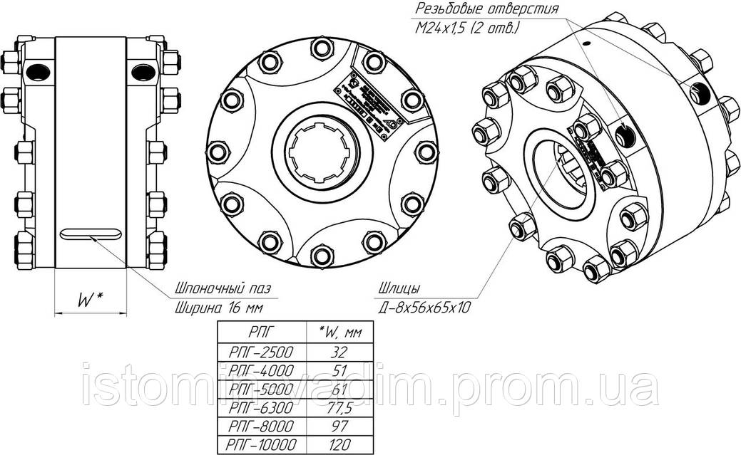
Kapanadze replication
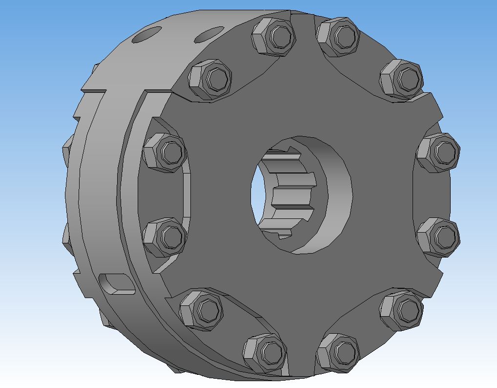
Kapanadze replication
But these aren't exactly the same as Kapanadze's; these are large and powerful hydraulic rotators for excavators.
Read the quote above: Kapanadze writes that his hydraulic pump is of an original design, not a mass-produced one.
 Author
Topic: Kapanadze replication (Read 256198 times)
Author
Topic: Kapanadze replication (Read 256198 times)
